BA-UI-EN-D33363.pdf - 第26页
26 D33363 | Date 01/2020 Operation and control 5.3 Loading the appliance Warning! When loading the appliance with an unsuitable load, poisonous or explosive vapours or gases may be produced. This could cause the applianc…
D33363 | Date 01/2020 25
Operation and control
5. Operation and control
5.1 Operating personnel
The appliance may only be operated by persons who are of legal age and have been instruct-
ed accordingly. Personnel who are to be trained, instructed or who are undergoing general
training may only work with the appliance under the continuous supervision of an experi-
enced person.
5.2 Opening the door
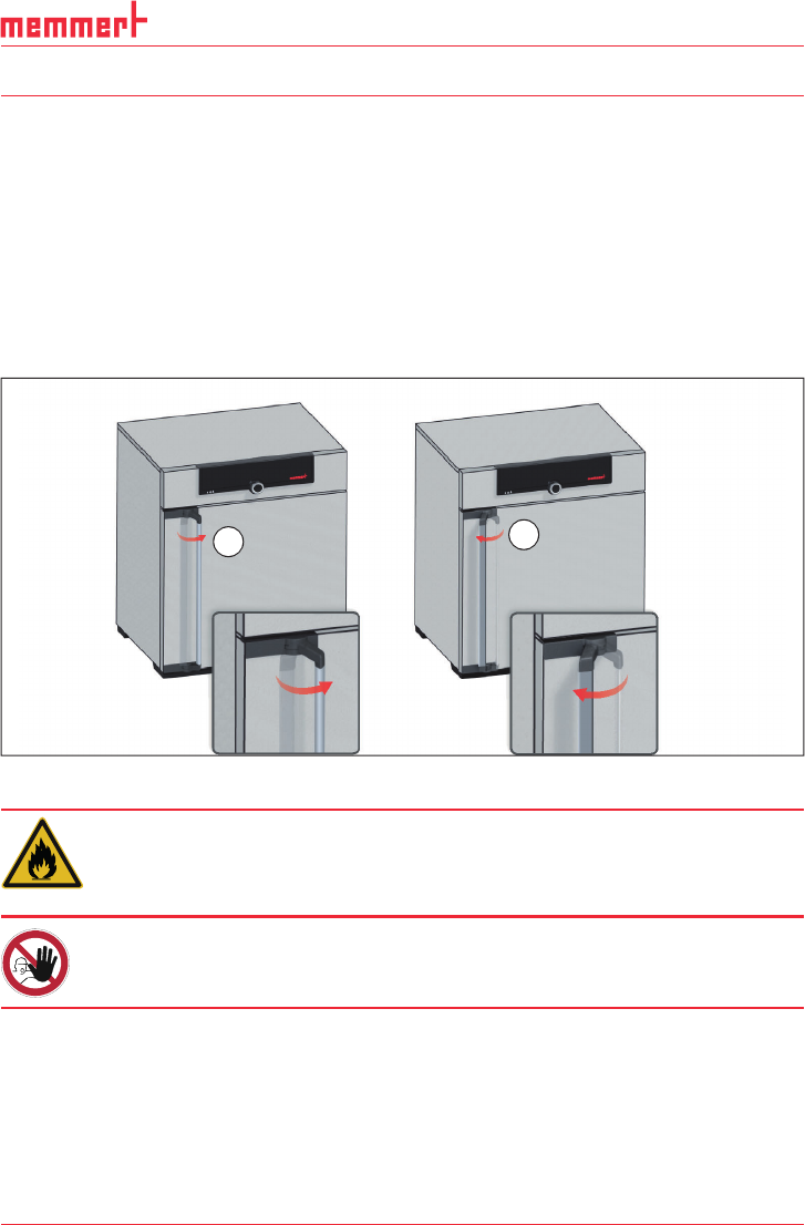
► To open the door, pull the door handle to the side (to the left or to the right, depending
on the door variation, see Fig. 13, A) and open the door completely.
► To close the appliance, push the door closed and the door handle to the side (B).
A
B
Fig. 13 Opening and closing the door
Warning!
If the door is open while the appliance is in operation, the appliance
may overheat and pose a fi re hazard. Do not leave the door open
during operation.
Warning!
In case of appliances of a certain size, you can get accidentally
locked in, which is life-threatening. Do not climb into the appliance!
26 D33363 | Date 01/2020
Operation and control
5.3 Loading the appliance
Warning!
When loading the appliance with an unsuitable load, poisonous
or explosive vapours or gases may be produced. This could cause
the appliance to explode, and persons could be severely injured or
poisoned. The appliance may only be loaded with materials which do
not form any toxic or explosive vapours when heated up and cannot
ignite (see also page 11). If there is any doubt as to the composi-
tion of materials, they must not be loaded into the appliance.
Caution:
Check the chamber load for chemical compatibility with the materials of the appliance
(see page 12).
Caution:
If the chamber load is wet or very humid, water may accumulate on the floor and dam-
age the heater. If wet, use a drip tray on the bottom of the tube.
Insert the sliding steel grids or sliding shelves. The maximum number or grids / shelves and the
load capacity are specified in the technical data overview on page 14.
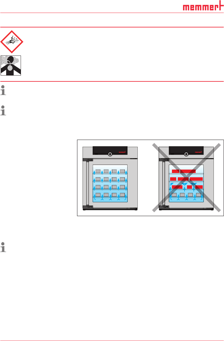
The chamber must not be
loaded too tightly, so that
proper air circulation in the
working chamber is guaran-
teed. Do not place any
chamber load on the floor,
touching the side walls or
right below the ceiling of the
working chamber (Fig. 14 , see
also the "correct loading"
sticker on the appliance).
In case of improper loading
(chamber loaded too tightly),
the set temperature may
be exceeded or it may take
longer until it is reached.
To achieve the correct heating capacity, the type of slide-in unit used – Grid or Shelf –
must be set in the menu under
SETUP (see page 41).
5.4 Operating the appliance
5.4.1 ControlCOCKPIT
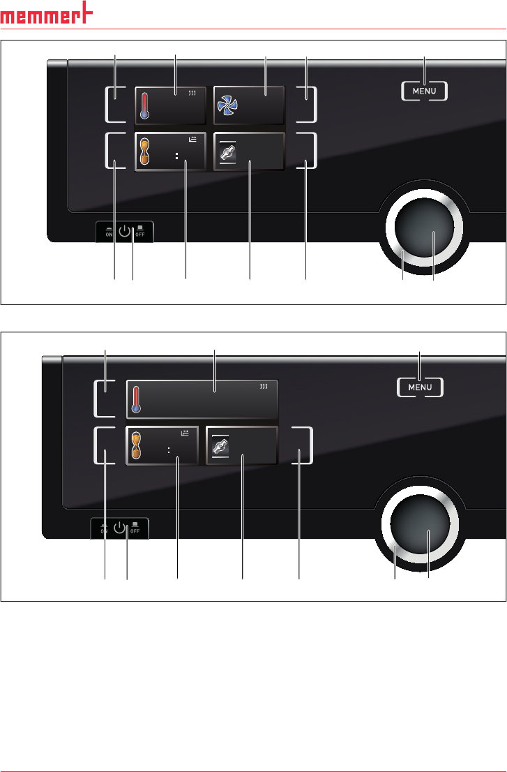
In manual operation, the desired parameters are entered at the ControlCOCKPIT on the front
of the appliance (Fig. 15 and Fig. 16 ). You can also make basic settings here (menu). Addition-
ally, warning messages are displayed, e.g. if the temperature is exceeded.
Fig. 14 Correct placement of the chamber load
D33363 | Date 01/2020 27
Operation and control
TIMER
End 14 : 45
44h:44m
180.4 °C
TEMP
Set 180
.4 °C
20%
FLAP
FAN
%
0
FLAP
40 %
53 412
TIMER
30m04h
End
13:30 23.11.
11 1267 8 9 10
Fig. 15 ControlCOCKPIT for UF.../IF... appliances in operating mode
180.0 °C
Set 180.9 °C
TEMP
TIMER
End 14 : 45
44h:44m
FLAP
FLAP
40 %
12 5
TIMER
30m04h
End
13:30 23.11.
10 11 1267 8 9
Fig. 16 ControlCOCKPIT for UN.../IN... appliances in operating mode
1 Activation key for temperature setpoint
adjustment
2 Setpoint and actual temperature display
3 Fan speed display
4 Activation key for fan speed setting
5 Switch to menu mode (see page 36)
6 Activation key digital backwards counter
with target time setting, adjustable from 1
minute to 99 days
7 On/Off switch
8 Display digital backwards counter with
target time setting, adjustable from 1 min-
ute to 99 days
9 Air flap position display
10 Activation key for air flap position adjust-
ment
11 Turn control for setpoint adjustment
12 Confirmation key (accepts setting made
with the turn control)