OM-1241-005_w.pdf - 第113页
3-6 AIX-ML T-ID (C02) Tray Data Fig. C4-1 "T ray" Edit Window (C02_01) Fdr No. Shown are the feeder Nos. in the placement feeder location data. When the multi-layer tray feeder is connected, the feeder Nos. (Fd…
3-5
AIX-MLT-ID
2. Pattern Program
2.1 Description of Pattern Program
2.1.1 Placement Feeder Location Data
The "Tray" and "Tray Step" tabs in each "Feeder Base #" tab can be used to
set the placement feeder location data for the multi-layer tray feeder.
Note
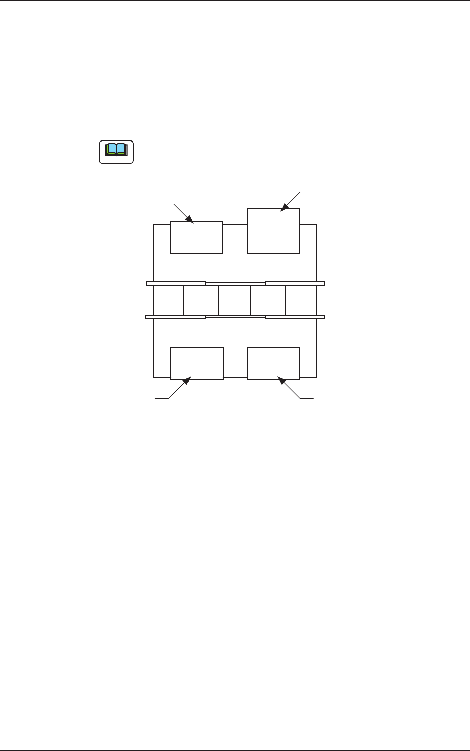
The following shows the positional relation between the feeder bases.
Front Side of Machine
Rear Side of Machine
Feeder Base #1
Feeder Base #2
Feeder Base #3
(Multi-Layer Tray Feeder)
Feeder Base #4
Fig. C4
0705-003
2. Pattern Program
3-6
AIX-MLT-ID
(C02) Tray Data
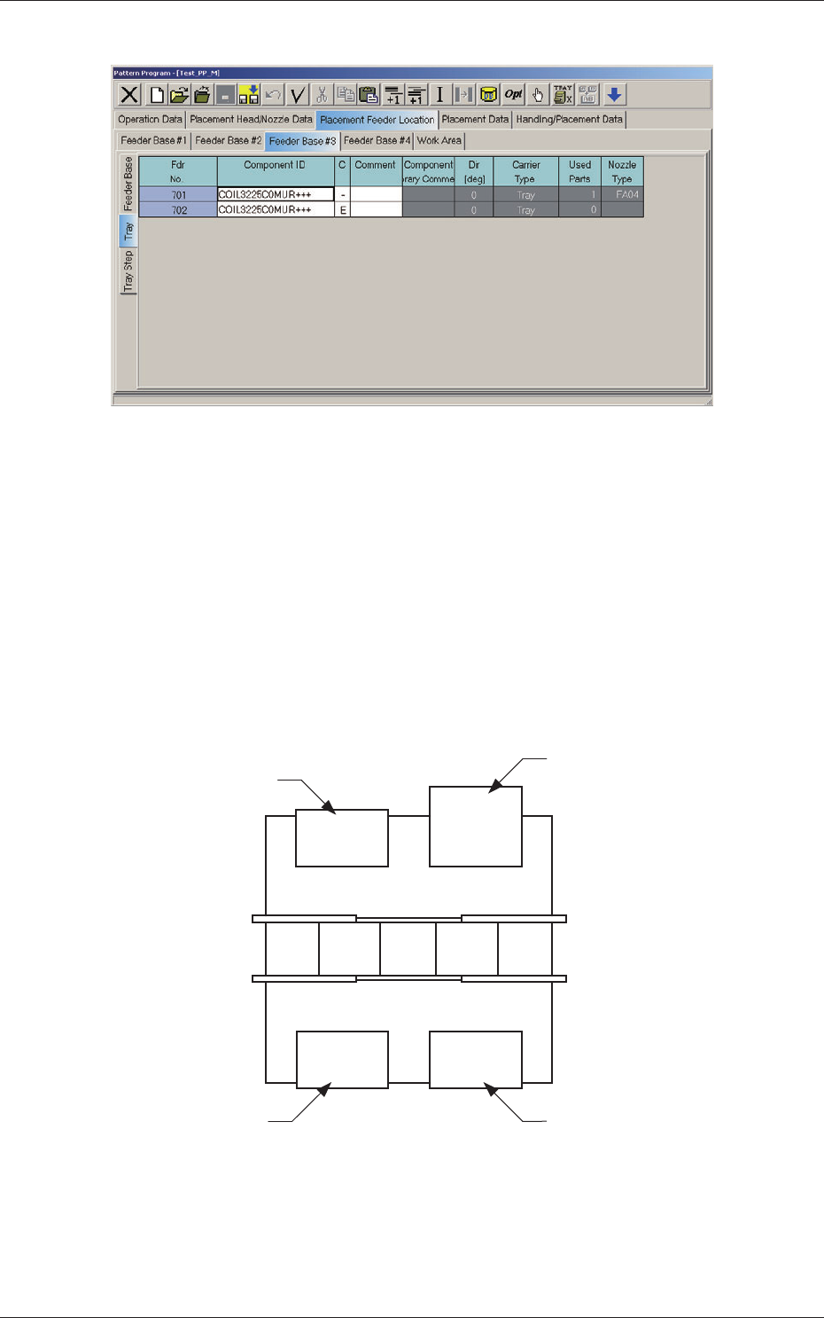
Fig. C4-1 "Tray" Edit Window
(C02_01) Fdr No.
Shown are the feeder Nos. in the placement feeder location data.
When the multi-layer tray feeder is connected, the feeder Nos. (Fdr
Nos.) become as follows.
Multi-Layer Tray Feeder #1 :
501 to 599
Multi-Layer Tray Feeder #2 :
6
01 to 699
Multi-Layer
Tray Feeder #3 :
701 to 799
Multi-Layer Tray Feeder #4 :
801 to 899
101 to 150 701 to 799
201 to 250 401 to 450
Front Side of Machine
Rear Side of Machine
Feeder Base #1
Feeder Base #2
Feeder Base #3
(Multi-Layer Tray Feeder)
Feeder Base #4
Fig. C5 Multi-Layer Tray Feeder #3 Connected
0804-004
2.1 Description of Pattern Program

3-7
AIX-MLT-ID
(C02_02) Component ID
Set component IDs in the text boxes.
(C02_03) C
Set control commands in the text boxes.
Notice
If a control command other than the following ones is used, the step
becomes invalid.
- (hyphen) :
This command handles the steps as those for the
placement feeder location data.
E :
This command shows the end of the placement feeder
location data.
The step where "E" is set is valid.
S :
This command invalidates the steps specied as
placement feeder location data.
X :
This command invalidates the steps specied as
placement feeder location data and shows the end of the
data.
(C02_05) Component Library Comment
Displayed are the comments entered in the component library data.
(C02_06) Dir [deg], Carrier Type
Displayed is the data specied in the component library data.
(C02_07)
Used Parts
Displayed is the number of components to be used for one unit PCB.
0705-003
2.1 Description of Pattern Program