OM-1241-005_w.pdf - 第122页
3-15 AIX-ML T-ID (5) Magazine #2 The upper magazine in the elevator unit can be adjusted. Parameters can be specied in the "Rack position [mm]", "Rack position (Center) [mm]", "Rack draw level […
3-14
AIX-MLT-ID
(4) Magazine #1
The lower magazine in the elevator unit can be adjusted.
Parameters can be specied in the "Rack position [mm]", "Rack
position (Center) [mm]", "Rack draw level [mm]", and "Rack putback
level [mm]" text boxes as Magazine #1 Offsets.
Rack position [mm]
This offset data can be used to adjust the loading position of Magazine
#1.
Observe the position where the elevator shaft has moved to the setup
position and enter proper values.
Note
To set the elevator position in a higher level, a minus value must be entered in the
text box.
Rack position (Center) [mm]
This offset data can be used to adjust the magazine change position.
Note
Follow the same adjustment as taken for the setup position to obtain the
numerical values and perform the adjustment based on the obtained values.
Rack draw level [mm]
This offset data is used to align the traverse chute in height with the
step (stage) of the tray when a pallet is drawn from Magazine #1 to the
traverse chute.
The entered offset value is reected on the travel of the elevator shaft
when the elevator is moved for the alignment of the pallet drawing step
(pallet drawing from Magazine #1).
Note
To set the elevator position in a higher level, a minus value must be entered in the
text box.
Rack putback level [mm]
This offset data is used to align the traverse chute in height with the step
(stage) of the tray when a pallet is put back from the traverse chute to
Magazine #1.
The entered offset value is reected on the travel of the elevator shaft
when the elevator is moved for the alignment of the pallet returning step
(pallet put back to Magazine #1).
Note
To set the elevator position in a higher level, a minus value must be entered in the
text box.
0705-003
4.1 Offset Data
3-15
AIX-MLT-ID
(5) Magazine #2
The upper magazine in the elevator unit can be adjusted.
Parameters can be specied in the "Rack position [mm]", "Rack
position (Center) [mm]", "Rack draw level [mm]", and "Rack putback
level [mm]" text boxes as Magazine #2 Offsets.
Rack position [mm]
This offset data can be used to adjust the loading position of Magazine
#2.
Note
Follow the same adjustment as taken for the setup position of Magazine #1 to
obtain the numerical values and perform the adjustment based on the obtained
values.
Rack position (Center) [mm]
This offset data can be used to adjust the magazine change position.
Note
Follow the same adjustment as taken for the setup position of Magazine #1 to
obtain the numerical values and perform the adjustment based on the obtained
values.
Rack draw level [mm]
This offset data is used to align the traverse chute in height with the
step (stage) of the tray when a pallet is drawn from Magazine #2 to the
traverse chute.
Note
Follow the same procedure as described for "Rack draw level [mm]" of Magazine
#1.
Rack putback level [mm]
This offset data is used to align the traverse chute in height with the step
(stage) of the tray when a pallet is put back from the traverse chute to
Magazine #2.
Note
Follow the same procedure as described for "Rack putback level [mm]" of
Magazine #1.
0705-003
4.1 Offset Data
3-16
AIX-MLT-ID
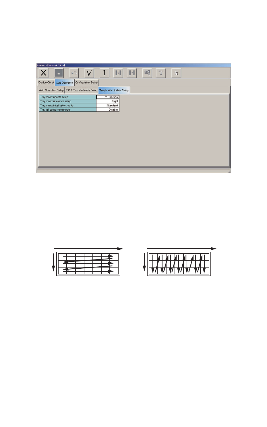
4.2 Auto Operation
4.2.1 Tray matrix update setup
When the "Tray Matrix Update Setup" subtab is pressed in the "Auto
Operation" tab sheet, the following subtab sheet appears.
Fig. C10 "Tray Matrix Update Setup" Subtab Sheet
(1) Tray matrix update setup
Select "X Direction" or "Y Direction" (direction in which components
should be taken out) in the text box.
In normal cases, "Y Direction" should be selected.
X
Y
Y
Selection of "Y Direction"Selection of "X Direction"
X
Fig. C11
4.2 Auto Operation
0804-004