OM-1241-005_w.pdf - 第195页
AIX-ML T-ID 5-34 Power Supply Section (Safety Circuit) 2 R 0705-003 A(M806WBR--0006) -1041 -1040 -1039 K1 K2 K1 K1 K2 K2 Control Circuit K2 K1 TH PWR 42 34 24 14 A2 A1 T1 1 T12 T21 T22 T31 T32 13 23 33 41 -1035 -1036 -10…
AIX-MLT-ID
5-33
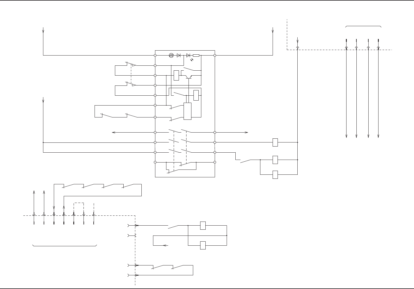
Power Supply Section (Safety Circuit) 2 L
0705-003 A(M806WBL--0006)
-1041
-1040
-1039
K1
K2
K1
K1
K2
K2
Control
Circuit
K2
K1
TH
PWR
42342414A2
A1
T11T12
T21 T22 T31 T32 13 23 33 41
-1035 -1036
-1033 -1032
-1031 -1030
-1034
-24G1
-10G
-10B
-24B1L
-1037
-1038
-1044
-1042
-1043
-1001
-1028-1027-1026
-1029
-1025
-1023
-1024
-K301
14 10
-K506
84
-K504
-K302
A1 A2
A2A1
-1015
-K002
22 21
-S0502
-S0502
1112
22 21
-K302 -K301
2221
-1007 -1018
-10A
10A
24G1
10G
:4
:3
:1
:2
X503
10B
24B1L
X502
:01
:02
:01
X507
:04
-K102-K101
2221 22 21
2 6
-K502
62616261
-K201 -K202
62
-K301
61
-K302
6162
:7
:3
:4
X504
:2
:1
:6
:5
A2A1
-K101
-K102
A2A1
10A
X507
COM
Relay 2 (UB21) Board
Safety Door Switch: (Upper)
Safety Door Switch: (Upper)
To -TR-U05 (UB14)
-X0525: 2
Main Body Safety
Cover Detection
From X2722: 2
To K501-5
To -TR-U04(CN6: 2)
Emergency Stop
Detection
From X2639: 2
Safety Relay K3
From X2611: 6
Safety Relay K3
To X2622: 2
From Main Machine of GX
Identification 1
Identification 2
From Main Machine of GX
From X20: 2
(Installation of Stage A)
From X23: 2
(Installation of Stage B)
From X20: 1
(Installation of Stage A)
From X23: 1
(Installation of Stage B)
From X36: 1
(Installation of Stage A)
From X37: 1
(Installation of Stage B)
From X36: 2
(Installation of Stage A)
From X37: 2
(Installation of Stage B)
From Terminal
EV (Upper)
EV2 Main Circuit
Power Supply ON
EV2 Load Power
ON Detection
To -TR-U05 (UB14)
-X0525: 1
Traverse Main Circuit
Power Supply ON
4.2 Electrical Circuit Diagrams Power Supply Section (Safety Circuit) 2 L
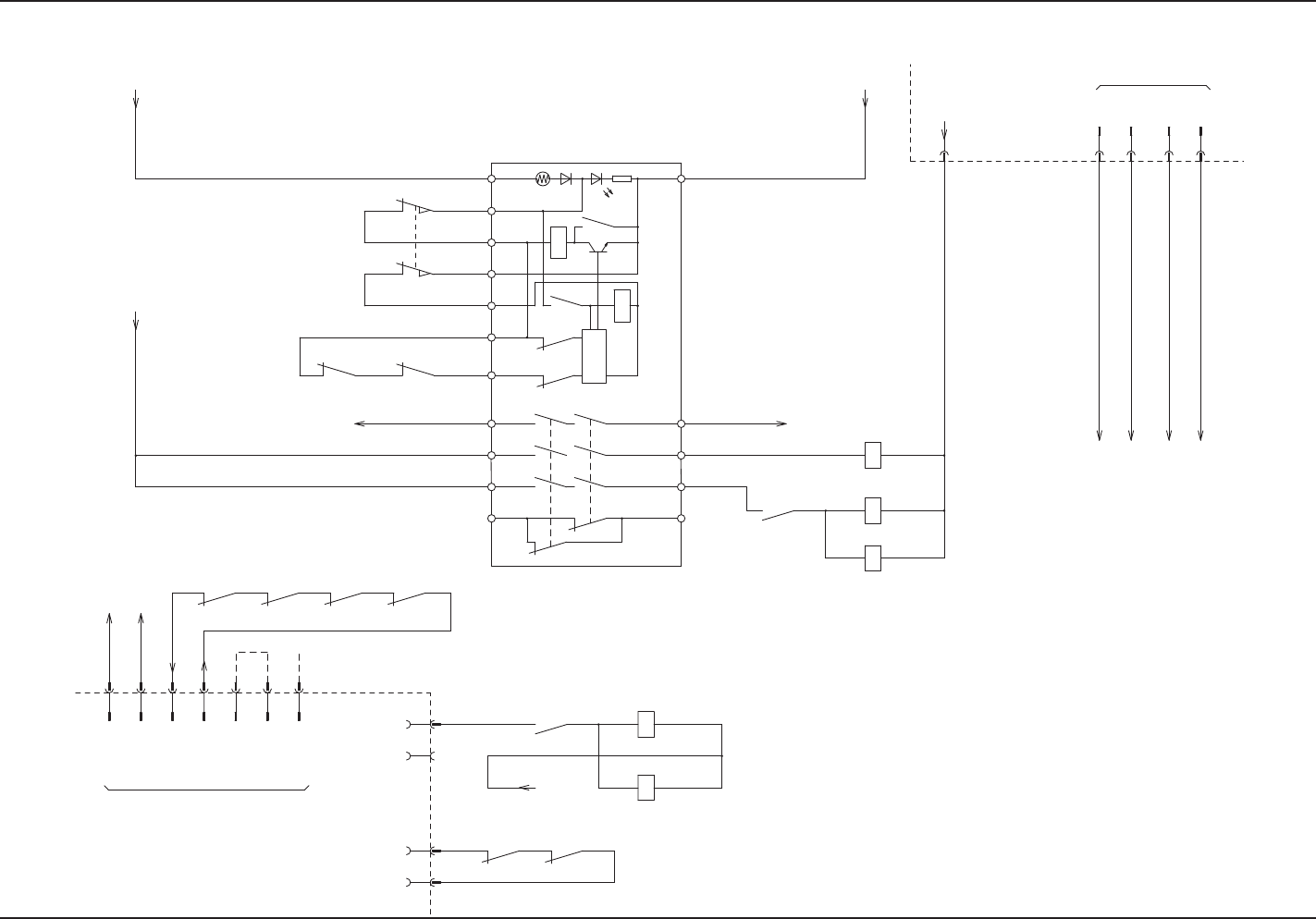
AIX-MLT-ID
5-34
Power Supply Section (Safety Circuit) 2 R
0705-003 A(M806WBR--0006)
-1041
-1040
-1039
K1
K2
K1
K1
K2
K2
Control
Circuit
K2
K1
TH
PWR
42342414A2
A1
T11T12
T21 T22 T31 T32 13 23 33 41
-1035 -1036
-1033 -1032
-1031 -1030
-1034
-1024
-1023
-24G1
-10G
-10B
-24B1R
-1025
-1029
-1026 -1027 -1028
-1037
-1038
-1001
-1043-1042
-1044
-K301
14 10
-K506
84
-K504
-K302
A1 A2
A2A1
-1015
-K002
22 21
-S0502
-S0502
1112
22 21
-K302 -K301
2221
:5
:6
:1
:2
X504
:4
:3
-1007 -1018
-10A
10A
24G1
10G
:4
:3
:1
:2
X503
10B
24B1R
:7
62 61
-K302
61
-K301
62
-K202-K201
61 62 61 62
X502
:01
A1 A2
-K102
-K101
A1 A2
-K502
62
212221 22
-K101 -K102
:04
X507
:01
:02
10A
X507
COM
Traverse Main Circuit
Power Supply ON
Relay 2 (UB21) Board
Safety Door Switch: (Upper)
Safety Door Switch: (Upper)
To -TR-U05 (UB14)
-X0525: 2
Main Body Safety
Cover Detection
From X2722: 2
To K501-5
To -TR-U04( CN6: 2)
Emergency Stop
Detection
From X2639: 2
Safety Relay K3
From X2611: 6
Safety Relay K3
To X2622: 2
From Main Machine of GX
Identification 1
Identification 2
From Main Machine of GX
From X20: 2
(Installation of Stage C)
From X23: 2
(Installation of Stage D)
From X20: 1
(Installation of Stage C)
From X23: 1
(Installation of Stage D)
From X36: 1
(Installation of Stage C)
From X37: 1
(Installation of Stage D)
From X36: 2
(Installation of Stage C)
From X37: 2
(Installation of Stage D)
From Terminal
EV (Upper)
EV2 Main Circuit
Power Supply ON
EV2 Load Power
ON Detection
To -TR-U05 (UB14)
-X0525: 1
4.2 Electrical Circuit Diagrams Power Supply Section (Safety Circuit) 2 R
AIX-MLT-ID
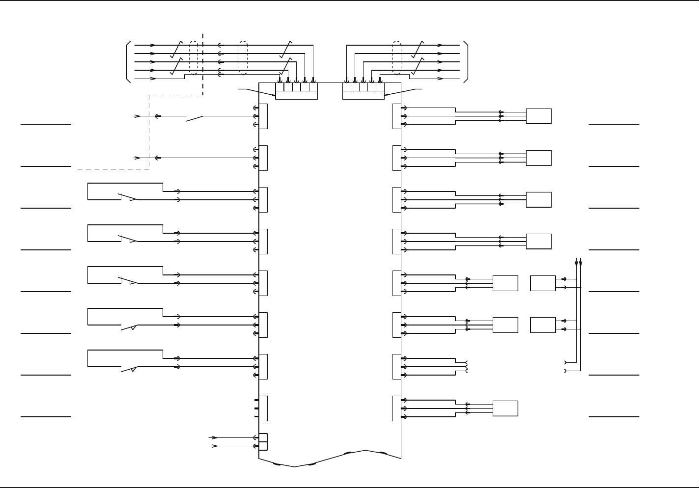
5-35
UA54 I/O Board ILB-IN 1 L
0705-003 A(M806WBL--0007)
/RX
RX
/TX
TX
FG
CN5
CN6
CN7
CN8
CN9
CN10
CN11
CN12
9
3 72
6
7
9 63
2
FG
TX
/TX
RX
/RX
-X0404-X0403
CN4CN3
ILB
IN
1
2
3
3
2
1
3
2
1
3
2
1
1
2
3
1
2
3
1
2
3
3
2
1
1
2
CN2
CN20
CN19
CN18
CN17
CN16
CN15
CN14
CN13
1
2
3
3
2
1
3
2
1
3
2
1
1
2
3
1
2
3
1
2
3
3
2
1
(UA54)
:7
:2
:5
:4
:7
:4
:5
:2
:3
:3
-S0505
-S0505
-10B
-24B1L
-X0402
:4
:3
31 32
-X0405
-X0406
-X0407
-X0408
-X0409
-X0410
-X0411
-0405
-0406
-0407
-0408
-0409
-0410
-0411
-S0504
-S0503
-S0502
-S0501
3231
3231
34
34
:3
:4
-S0504
-S0503
:6
:5
-S0502
:6
:5
-S0501
:6
:5
-X0413
-X0414
-X0415
-X0416
-X0417
-X0418
-0413
-0414
-0415
-0416
-0417
-0418
-0419
-0420
-B0420
-B0415
-B0414
-
OUT
+
-B0420
:1
:2
:3
:3
:2
:1
-B0419
:3
:2
:1
-B0418
+
OUT
-
-B0418
:3
:2
:1
-B0417
+
OUT
-
-B0417
:3
:2
:1
-B0416
+
OUT
-
-B0416
:3
:2
:1
-B0415
+
OUT
-
:3
:2
:1
-B0414
+
OUT
-
:3
:2
:1
-B0413
+
OUT
-
-B0413
-B0417T
-
+
-B0418T
-
+
-B0418T
:1
:2
:2
:1
-B0417T
:2
:1
-B0419T
-10B1
-24B1L
-TR-U04
15
-K501
-X505
:1
:2
:3
:4
:9
-X504
:1
:2
-X0501(CN1)
-TR-U05(UB14)EV,TV:I/O
Emergency Stop
Detection
Main Machine
Safety Cover
Detection
Safety Door (Lower)
Door Switch Detection
Safety Door (Upper)
Door Switch Detection
Safety Door (Magazine)
Door Switch Detection
Maintenance Cover
Open Detection LS1
Maintenance Cover
Open Detection LS2
RESERVED
D (D) ch2-1
-U09 (UB14) Positioning
-X0902 (CN2)
From Main Machine of GX
X2639: 2
(From K3 33)
-X2722: 2
(From -K4 33)
Pallet Chuck Claw Cylinder 1
[Clamping Side]
Pallet Chuck Claw Cylinder 1
[Unclamping Side]
Pallet Chuck Claw Cylinder 2
[Clamping Side]
Pallet Chuck Claw Cylinder 2
[Unclamping Side]
Ejected Palette Detection
(Traverse Side)
Pickup Error
Detection Sensor A
Pickup Error
Detection Sensor B
(Option)
Pickup Error
Detection Sensor C
4.2 Electrical Circuit Diagrams UA54 I/O Board ILB-IN 1 L