OM-1241-005_w.pdf - 第206页
AIX-ML T-ID 5-45 UB26 Component Reload Switch Board (Upper) R 0705-003 A(M806WBR--0012) CN10 CN1 2 1 -24B1R -10B CN1 1 CN12 CN13 CN14 CN15 CN16 CN17 CN18 CN19 CN20 CN21 CN22 CN23 CN25 CN24 OUT IN -TR-U07 -X0603 :7 :4 :5 …
AIX-MLT-ID
5-44
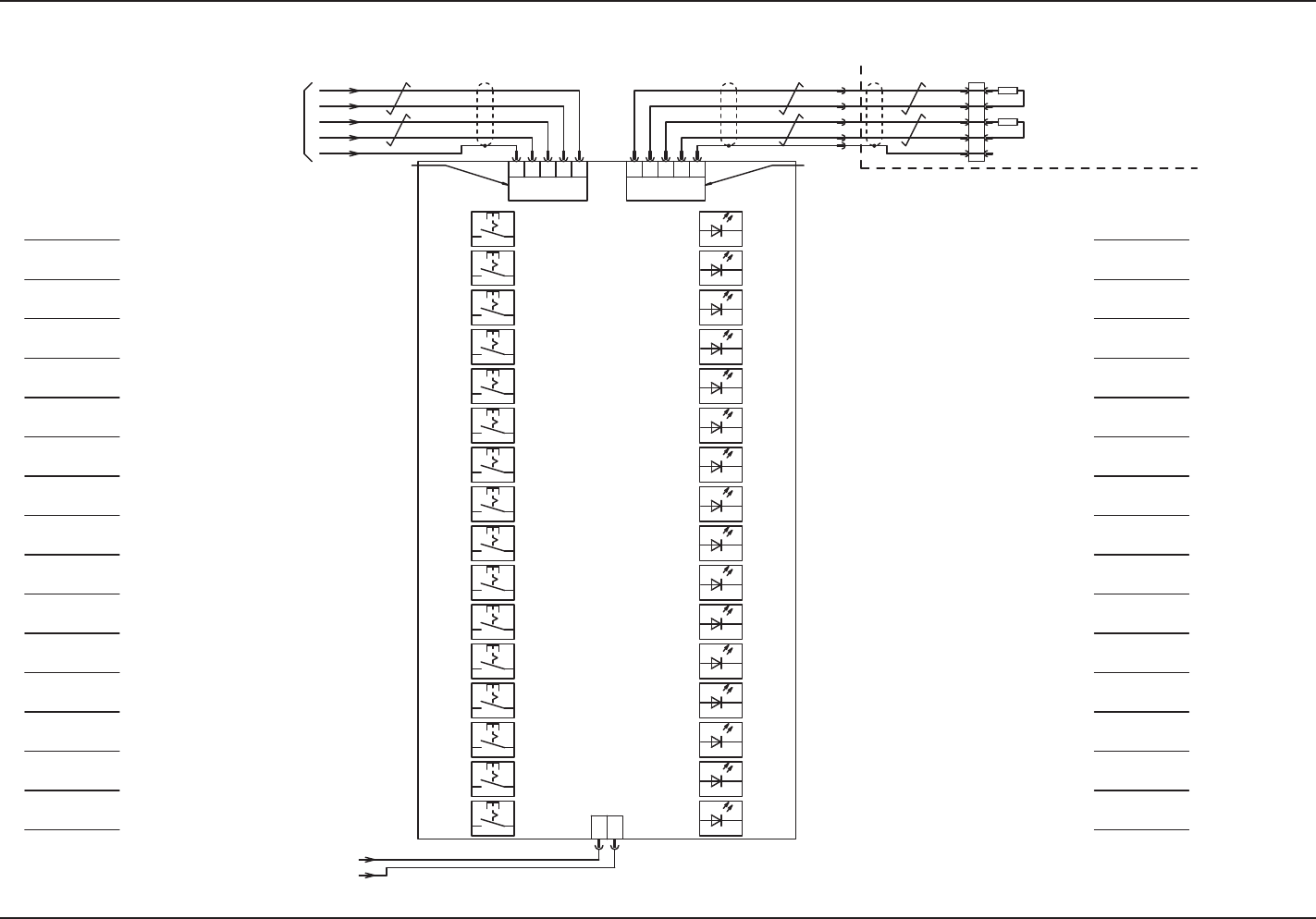
UB26 Component Reload Switch Board (Upper) L
0705-003 A(M806WBL--0012)
RJ45
CN1
21
-24B1L
-10B
OUTIN
-TR-U07
-X0603
:7
:4
:5
:2
:3
724 3553 427
-X0702-X0701
RX
/RX
TX
/TX
FG
FG
/TX
TX
/RX
RX
CN2BCN2A
(UB26)
S01
S02
S04
S03
S07
S08
S06
S05
S13
S14
S16
S15
S11
S12
S10
S09
LED01
LED02
LED04
LED03
LED07
LED08
LED06
LED05
LED13
LED14
LED16
LED15
LED11
LED12
LED10
LED09
:7
:2
:5
:4
:3
-X505
:5
:6
:7
:8
:9
-X10902
100Ω,1/2W
100Ω,1/2W
-TR-U06(UB26)
Component Reload 1
-X0602(CN2A/2B)
GX Main Machine,
Terminating Resistance
All Reload Switch
Reload Switch 1
Reload Switch 2
Reload Switch 3
Reload Switch 4
Reload Switch 5
Reload Switch 6
Reload Switch 7
Reload Switch 8
Reload Switch 9
Reload Switch 10
Reload Switch 11
Reload Switch 12
Reload Switch 13
Reload Switch 14
Reload Switch 15
Material Shortage Indicator
Lamp 1
Material Shortage Indicator
Lamp 2
Material Shortage Indicator
Lamp 3
Material Shortage Indicator
Lamp 4
Material Shortage Indicator
Lamp 5
Material Shortage Indicator
Lamp 6
Material Shortage Indicator
Lamp 7
Material Shortage Indicator
Lamp 8
Material Shortage Indicator
Lamp 9
Material Shortage Indicator
Lamp 10
Material Shortage Indicator
Lamp 11
Material Shortage Indicator
Lamp 12
Material Shortage Indicator
Lamp 13
Material Shortage Indicator
Lamp 14
Material Shortage Indicator
Lamp 15
All Reload Indicator Lamp
Component Reload
Switch (Upper)
4.2 Electrical Circuit Diagrams UB26 Component Reload Switch Board (Upper) L
AIX-MLT-ID
5-45
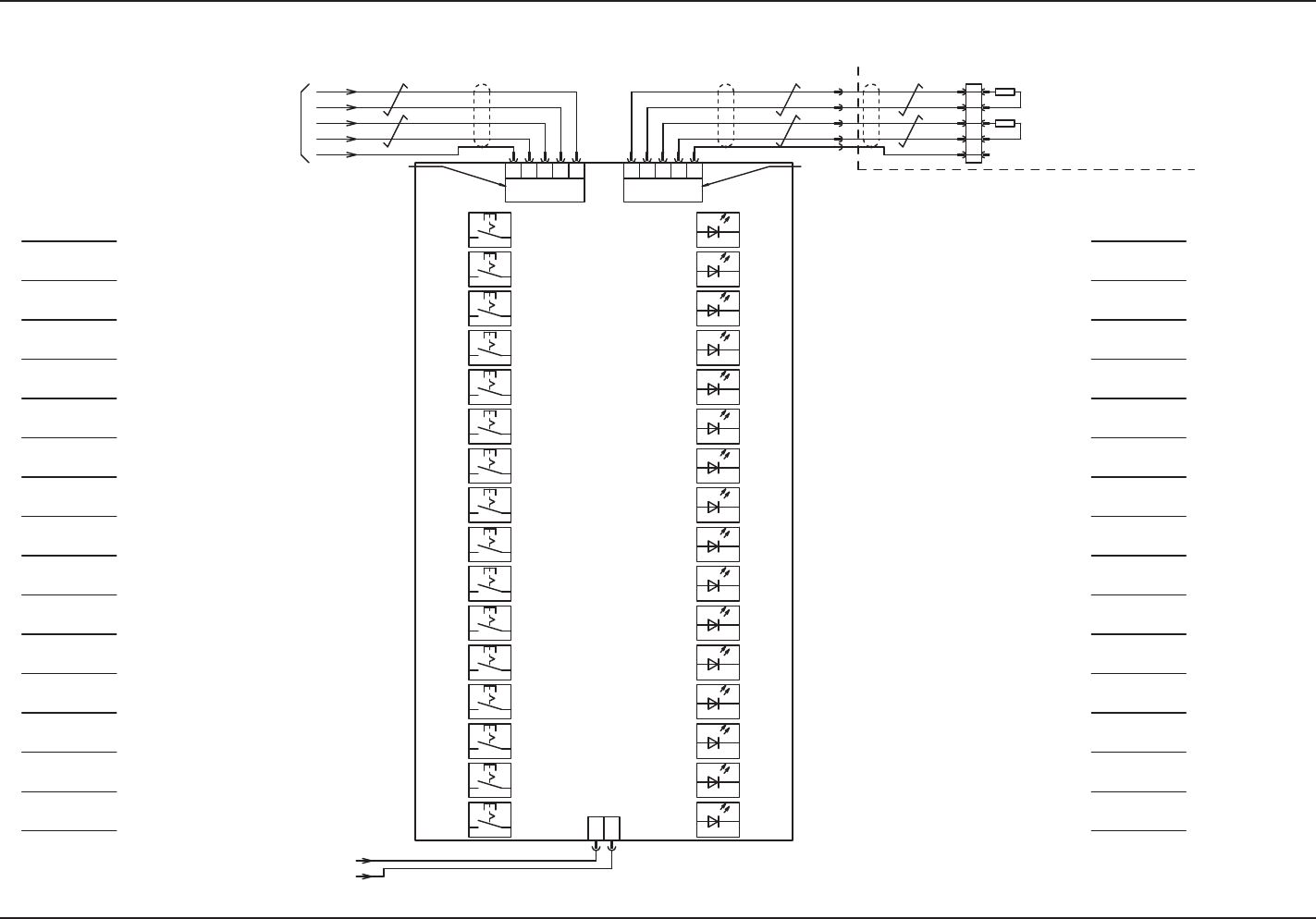
UB26 Component Reload Switch Board (Upper) R
0705-003 A(M806WBR--0012)
CN10
CN1
21
-24B1R
-10B
CN11
CN12
CN13
CN14
CN15
CN16
CN17
CN18
CN19
CN20
CN21
CN22
CN23
CN25
CN24
OUTIN
-TR-U07
-X0603
:7
:4
:5
:2
:3
724 3553 427
-X0702-X0701
RX
/RX
TX
/TX
FG
FG
/TX
TX
/RX
RX
CN2BCN2A
(UB26)
S01
S02
S04
S03
S07
S08
S06
S05
S13
S14
S16
S15
S11
S12
S10
S09
LED01
LED02
LED04
LED03
LED07
LED08
LED06
LED05
LED13
LED14
LED16
LED15
LED11
LED12
LED10
LED09
:5
:6
:7
:8
:9
:7
:2
:5
:4
:3
-X10902
100Ω,1/2W
100Ω,1/2W
-X505
-X505
All Reload Switch
Reload Switch 1
Reload Switch 2
Reload Switch 3
Reload Switch 4
Reload Switch 5
Reload Switch 6
Reload Switch 7
Reload Switch 8
Reload Switch 9
Reload Switch 10
Reload Switch 11
Reload Switch 12
Reload Switch 13
Reload Switch 14
Reload Switch 15
-TR-U06 (UB26)
Component Reload 1
-X0602 (CN2A/2B)
Component Reload
Switch (Upper)
Material Shortage Indicator
Lamp 1
Material Shortage Indicator
Lamp 2
Material Shortage Indicator
Lamp 3
Material Shortage Indicator
Lamp 4
Material Shortage Indicator
Lamp 5
Material Shortage Indicator
Lamp 6
Material Shortage Indicator
Lamp 7
Material Shortage Indicator
Lamp 8
Material Shortage Indicator
Lamp 9
Material Shortage Indicator
Lamp 10
Material Shortage Indicator
Lamp 11
Material Shortage Indicator
Lamp 12
Material Shortage Indicator
Lamp 13
Material Shortage Indicator
Lamp 14
Material Shortage Indicator
Lamp 15
All Reload Indicator Lamp
GXH Main Body,
Terminating Resistance
4.2 Electrical Circuit Diagrams UB26 Component Reload Switch Board (Upper) R
AIX-MLT-ID
5-46
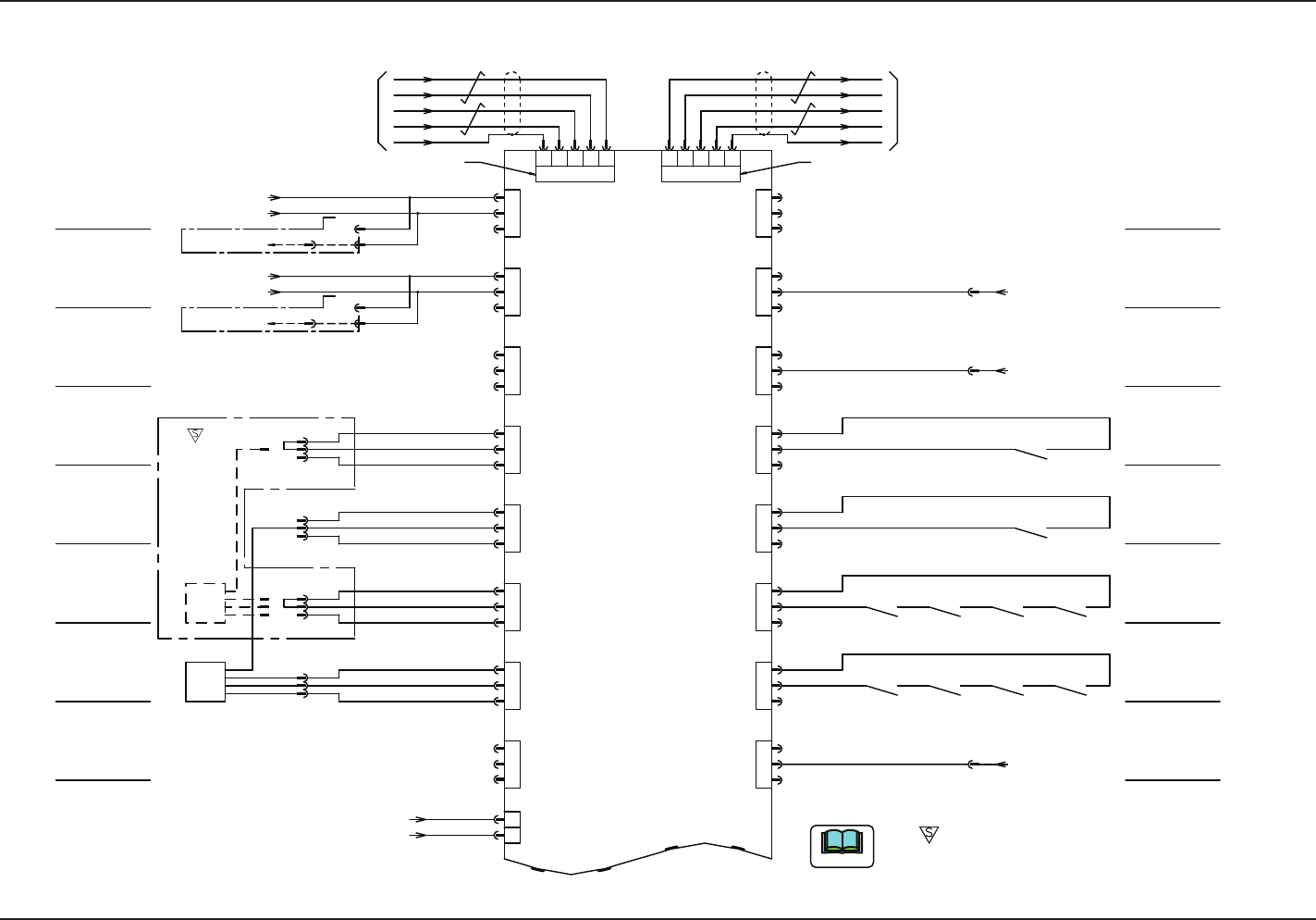
UA54 I/O Board ILB-IN 1 L (Rear Left Side) G-S014-01 (For Maine Machine)
0705-003 -(M803WBL-A2008)
/RX
RX
/TX
TX
FG
-X0505
-X0506
-X0508
-X0509
-X0510
-X0511
X2639:1 (From K3 34)
X2639:2 (From K3 33)
X2722:1 (From K4 34)
X2722:2 (From K4 33)
-U05
CN5
CN6
CN7
CN8
CN9
CN10
CN11
CN12
Lifted Suppressor
Detection (A)
Lifted Suppressor
Detection (B)
-502
-501
-506
-507
-505
-504
9
3 72
6
7
9 63
2
FG
TX
/TX
RX
/RX
-X0504-X0503
CN4CN3
10B
24B1L
ILB
IN
1
2
3
3
2
1
3
2
1
3
2
1
1
2
3
1
2
3
1
2
3
3
2
1
24B1L
10B
10B
24B1L
10B
24B1L
10B
24B1L
1
2
CN2
-X0502
9 5
9 5
-K48
-K48
-512
802
803
-Q223 -Q222
-513
805
806
-Q223 -Q222
804
-Q221 -Q201
801
-Q221 -Q201
-515
-514
-510
-511
-516
Nozzle U/D Interlock (MA)
Nozzle U/D Interlock (MB)
CN20
CN19
CN18
CN17
CN16
CN15
CN14
CN13
From MA-B3103 OUT
-X10514
-X10515
-X10520
-X0520
-X0515
-X0514
-X0513
-X0519
-X0518
-X0517
-X0516
1
2
3
3
2
1
3
2
1
3
2
1
1
2
3
1
2
3
1
2
3
3
2
1
10B
10B
10B
10B
(UA54)
:7
:2
:5
:4
:9
:2
:6
:3
:7
:3
10B
10B
BA
BB
BA BA BABA
14 13 13 13
13131314
14 14
1414
ac
ac
BB BBBBBB
X504
:1
-X1504
:1
:2
:2
:1
-X1504
:2
X504
-X10511
-X10510
-B0510
-B0510
DA
DB
+
-
OUT1
:2
:3
:1
+
-
OUT1
:2
:3
:1
:1
:3
:2
:1
:3
:2
-X10508
-X10509
OUT2
OUT2
D(L) ch1-1
BL ch1-1
-X0710(CN10)
-X1202(CN2)
-U12 (UB14) Main Machine
Safety Monitor for
Left Cover
Emergency Stop
Safety Monitor
-U07(UA53)I/F
Beam B CB Error Monitor
Beam A CB Error Monitor
CB Error
(A-Y1)
CB Error
(A-Y2)
CB Error
(B-Y1)
CB Error
(B-Y2)
CB Error (Beam B Integral
)
CB Error
(B-X)
CB Error (Beam A Integral
)
CB Error
(A-X)
Beam A Main Power OFF
Detection
Beam B Main Power OFF
Detection
Head U/D Interlock (MA)
RESERVED
Disengaged Latch
Detection (A)
Disengaged Latch
Detection (B)
RESERVED
RESERVED
Multi-layer Tray (L)
Multi-layer Tray (L)
Brown
Orange
Blue
Black
Brown
Orange
Blue
Black
From A-B3101 OUT
From B-B3101 OUT
Note
The -marked area is specially specified.
4.2 Electrical Circuit Diagrams UA54 I/O Board ILB-IN 1 L (Rear Left Side) G-S014-01 (For Maine Machine)