OM-1241-005_w.pdf - 第187页
AIX-ML T-ID 5-26 4.2 Electrical Circuit Diagrams BlockCongurationDrawingL 4.2ElectricalCircuitDiagramsBlockCongurationDrawingL 0705-003 -(M806WBL--0001) I/O I/O I/O SSCNET SSCNET SSCNET U83 MR-MC10 MR-MC10 U…
5-25
AIVX-MLT-P
0705-003
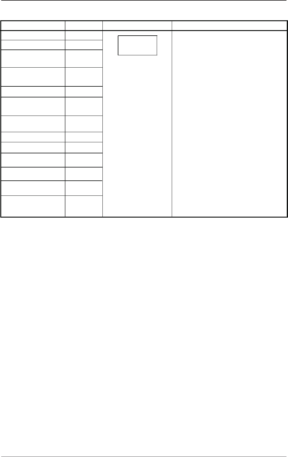
4.1 Electrical and Electronic Symbols
Name
Symbols
Graphical Symbols Remarks
Noise Filter
Servomotor Driver
Stepping Motor Driver
Speed Control Pack
Switching Power
Brake Power for
Servomotor
Lightning Surge
Protector
Unit PCB
Hard Disk Drive
Floppy Disk Drive
The graphical symbol generally
represents a unit.
Different circuit symbols are used
according to the classification of
electrical components.
Z
A
A
A
G
G
F
U
D
D
U
U
Other Units A
Inverter
Converter
AIX-MLT-ID
5-26
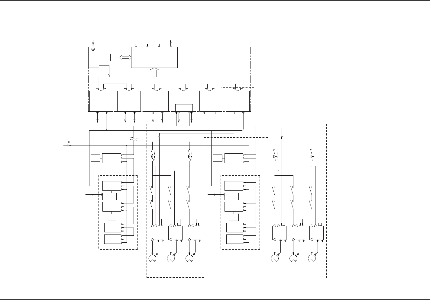
4.2 Electrical Circuit Diagrams
BlockCongurationDrawingL
4.2ElectricalCircuitDiagramsBlockCongurationDrawingL
0705-003 -(M806WBL--0001)
I/OI/OI/O SSCNETSSCNET SSCNET
U83
MR-MC10MR-MC10
U82U84
MR-MC10
I/OSSCNET
U90
MR-MC10
HLS
-X90C1
-X90C2
-K301-K302
-Q101-K101
-K102
-Q201-K201-K202
-K202 -K201 -Q201
-K102
-K101 -Q101
-K302 -K301
CH2 CN1
CH1 CN1
CH2 CN2
CH1 CN2
-X8401
-X8403
-X8301
-X8303
-X8201
-X8203
-X9003
-X9001
HLS
3
M
3
M
3
M
3
M
3
M
3
M
PCI BUS
SDD
U86U85
HLSB-PCI
1 2
HLSC1
+5V
+3.3V
+5V
+12V
-12V
(-5V)
VGACOM1
CPU2-B
U81
/ MS
BASE-T
-A01-A03-A02
SW+IO(UB26)
16/16 <U>
16/16 <D>
SW+IO(UB26)
IO(UB14)
16/16
32/16
24A
-M02
-M03
-M01
ILB(UA54)
TR-U04:48,49
TR-U05:50
TR-U06:51
TR-U07:52
-M02
-M03
-M01
-A02 -A03 -A01
ILB(UA54)
24A
32/16
16/16
IO(UB14)
SW+IO(UB26)
16/16 <D>
16/16 <U>
SW+IO(UB26)
TR-U04:48,49
TR-U05:50
TR-U06:51
TR-U07:52
AC200V
-24B1L
(L121,221,321)
3
φ AC200V
FP-G100L
FP-G100L
FP-G100R
To HUB (U72)
Control (STAGE1)
Feeder Serial
(6 Axes s2ch) (6 Axes s2ch)
(6 Axes s2ch)
(6 Axes s2ch)
Positioning
(UA14)
U09
Multi-Layer Tray
(at installation of Stage A)
Sensor
Solenoid
Valve, etc.
Positioning
(UA14)
U09
Relay Circuit
(Safety Circuit,
etc.)
Relay Circuit
(Safety Circuit,
etc.)
Sensor
Solenoid
Valve, etc
Multi-Layer Tray
(at installation of Stage A)
FP-G100R
Multi-Layer Tray
(at installation of Stage B)
Traverse
Elevator 2
Elevator 1
With Brake
With Brake
Traverse
Elevator 2
Elevator 1
With Brake
With Brake
Elevator 1
(Lower)
Elevator 2
(Upper)
Traverse
Multi-Layer Tray
(at installation of Stage B)
Sensor
Solenoid
Valve, etc.
Sensor
Solenoid
Valve, etc.
Elevator 1
(Lower)
Elevator 2
(Upper)
Traverse
AIX-MLT-ID
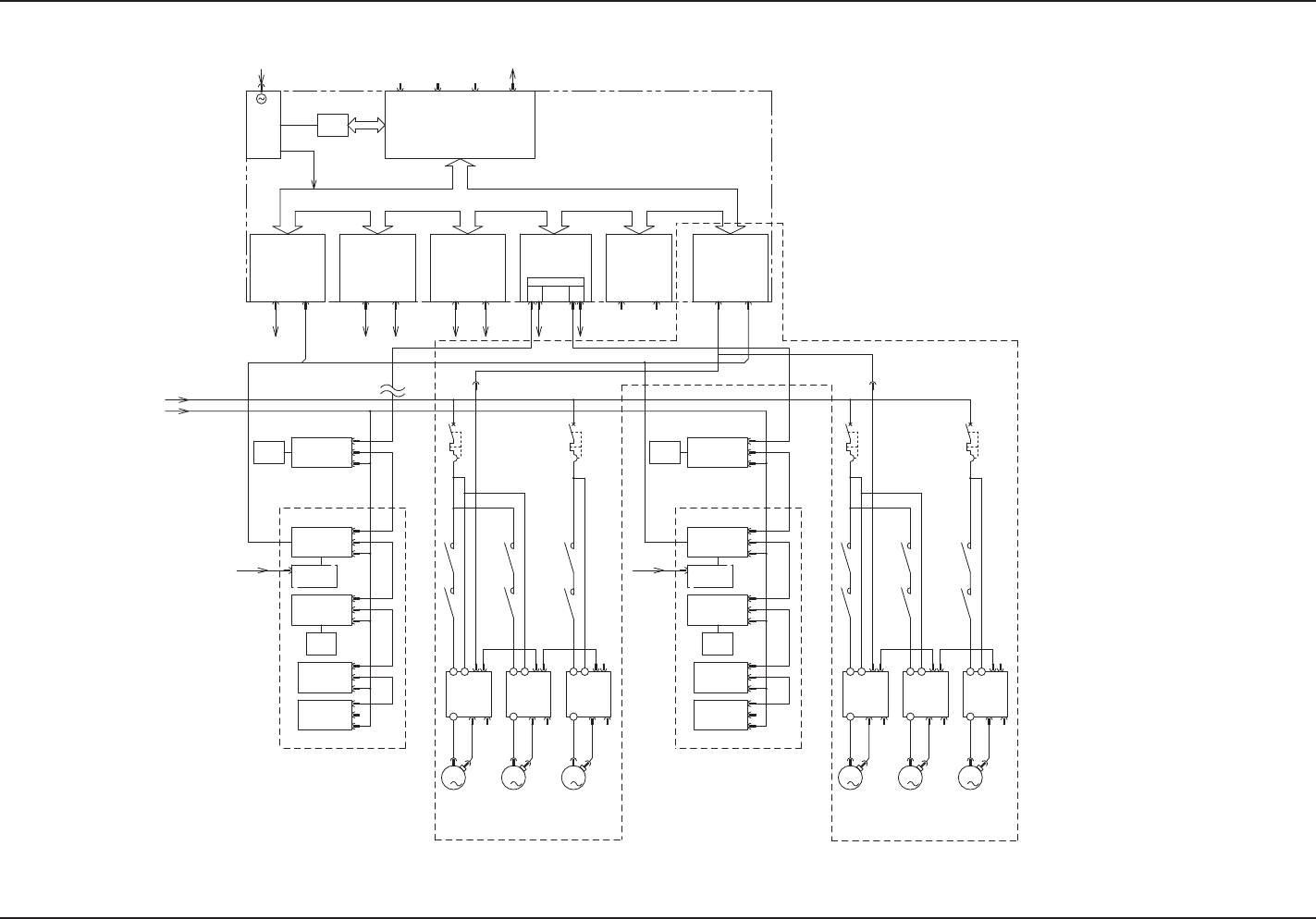
5-27
4.2ElectricalCircuitDiagramsBlockCongurationDrawingR
BlockCongurationDrawingR
0705-003 -(M806WBR--0001)
I/OI/OI/O SSCNETSSCNET SSCNET
U83
MR-MC10MR-MC10
U82U84
MR-MC10
I/OSSCNET
U90
MR-MC10
HLS
-X90C1
-X90C2
-K301-K302
-Q101-K101
-K102
-Q201-K201-K202
-K202 -K201 -Q201
-K102
-K101 -Q101
-K302 -K301
CH2 CN1
CH1 CN1
CH2 CN2
CH1 CN2
-X8401
-X8403
-X8301
-X8303
-X8201
-X8203
-X9003
-X9001
HLS
3
M
3
M
3
M
3
M
3
M
3
M
PCI BUS
SDD
U86U85
HLSB-PCI
1 2
HLSC1
+5V
+3.3V
+5V
+12V
-12V
(-5V)
VGACOM1
CPU2-B
U81
/MS
BASE-T
-A01-A03-A02
SW+IO(UB26)
16/16 <U>
16/16 <D>
SW+IO(UB26)
IO(UB14)
16/16
32/16
24A
-M01
-M03
-M02
ILB(UA54)
TR-U04:48,49
TR-U05:50
TR-U06:51
TR-U07:52
-M02
-M03
-M01
-A02 -A03 -A01
ILB(UA54)
24A
32/16
16/16
IO(UB14)
SW+IO(UB26)
16/16 <D>
16/16 <U>
SW+IO(UB26)
TR-U04:48,49
TR-U05:50
TR-U06:51
TR-U07:52
AC200V
-24B1R
(L121,221,321)
3φ AC200V
-M02
-M03
-M01
-M02
-M03
-M01
FP-G100R
FP-G100R
FP-G100L
To HUB (U72)
Control (STAGE 2)
Feeder Serial
(6 Axes s2ch)
(6 Axes s2ch)
(6 Axes s2ch)
(6 Axes s2ch)
Positioning
(UA14)
U09
Multi-Layer Tray
(at installation of Stage C)
Sensor
Solenoid
Valve, etc.
Sensor
Solenoid
Valve, etc.
Positioning
(UA14)
U09
Relay Circuit
(Safety Circuit,
etc.)
Relay Circuit
(Safety Circuit,
etc.)
Multi-Layer Tray
(at installation of Stage C)
FP-G100L
Multi-Layer Tray
(at installation of Stage D)
Traverse
Elevator 2
Elevator 1
With Brake
With Brake
Traverse
Elevator 2
Elevator 1
With Brake
With Brake
Multi-Layer Tray
(at installation of Stage D)
Sensor
Solenoid
Valve, etc.
Sensor
Solenoid
Valve, etc.
Elevator 1
(Lower)
Elevator 2
(Upper)
Traverse
Elevator 1
(Lower)
Elevator 2
(Upper)
Traverse