MDO3000 Programmer Manual.pdf - 第1013页
Status and Events T able 3-2: SBR Bit Functions (cont.) Bit Function 4M A V Message Available. Shows that output is available in the O utput Queue. 3 ———— Not used. 2 ———— Not used. 1–0 ———— Not used. Enable Reg isters D…
Status and Events
Table 3-1: SESR
Bit Functions
Bit Function
7 (MSB) PON Power On. Show
s that the oscilloscope was powered on.
On completion, the diagnostic s elf tests also set this bit.
6
URQ
User Request
.
Indicates that an application event has
occurred. *See note.
5
CME
Command Error. Shows that an error o ccurred while
the oscilloscope was parsing a c ommand or query.
4 EXE
Execution Error. Shows that an error executing a
command or
query.
3DDE
Device Err
or. Shows that a device error occurred.
2
QYE
Query Error. Either an attempt was made to read the
Output Qu
eue when no data was present or pending, or that
data in the Output Queue was lost.
1
RQC
Request C
ontrol.
This is not used.
0 (LSB) OPC Operation Complete. Shows that the operation
is complete. This bit is set when all pending operations
comple
te following an *OPC command.
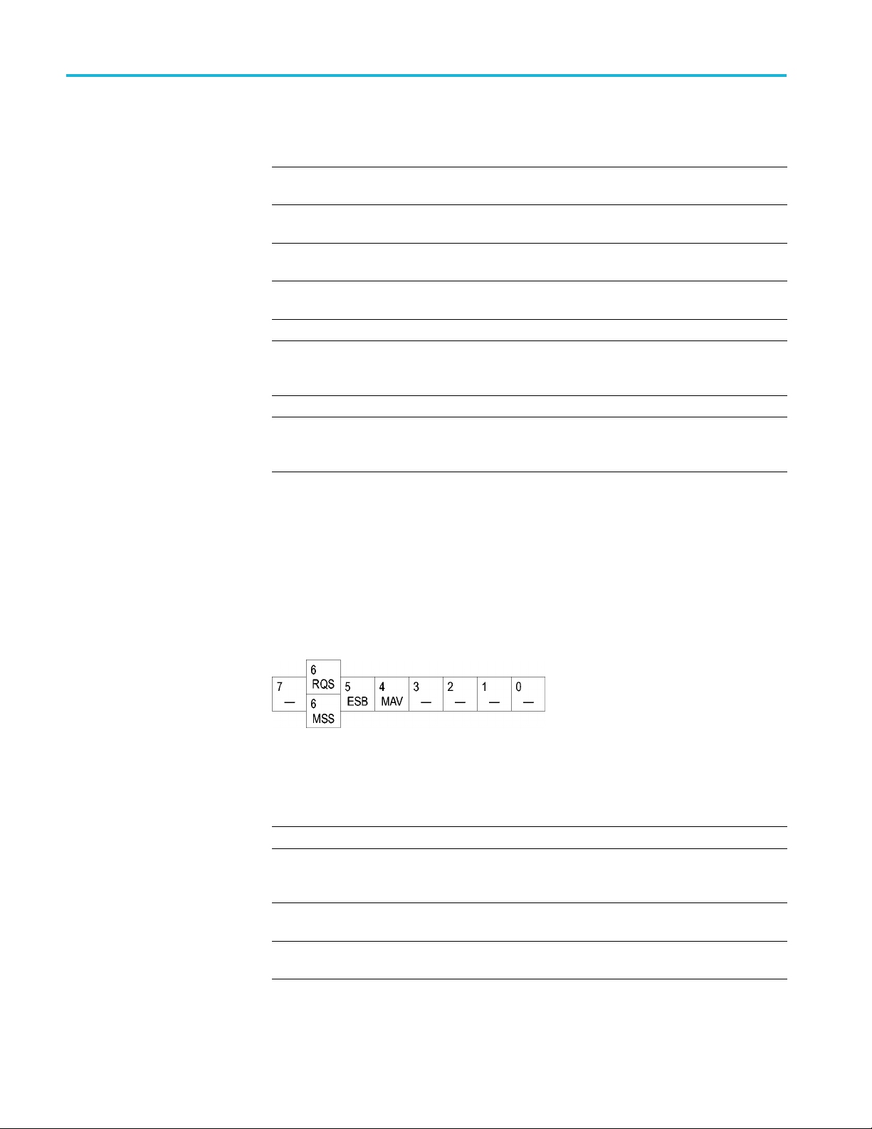
The Status Byte Register (SBR). Records whether output is available in the Output
Queue, whether the oscilloscope requests service, and whether the SESR has
recorded any events.
Use a Serial Poll or the *STB? query to read the contents of the SBR. The bits in
the SBR are set and cleared depending on the contents of the SESR, the Event
Status Enable Register (ESER), and the Output Queue. When you use a Serial
Poll to obtain the SBR, bit 6 is the RQS bit. When you use the *STB? query to
obtain the SBR, bit 6 is the MSS bit. Reading th
e SBR does not clear the bits.
Figure 3-2: The Status Byte Register (SBR)
Table 3-2: SBR Bit Functions
Bit Function
7(MSB)
————
Not used.
6
RQS
Request Service. Obtained from a serial poll. Shows
that the oscilloscope requests service from the GPIB
controller.
6
MSS
Master Status Summary. Obtained from *STB?
query. Summarizes the ESB and MAV bits in the SBR.
5
ESB
Event Status Bit. Shows that status is enabled and
present in the SESR.
3-2 MDO4000/B/C, MSO/DPO4000B and MDO3000 Series Oscilloscopes Programmer Manual
Status and Events
Table 3-2: SBR Bit Functions (cont.)
Bit Function
4MAV
Message Available. Shows that output is available
in the O utput Queue.
3
————
Not used.
2
————
Not used.
1–0
————
Not used.
Enable Registers
DESER, ESER, and SRER allow you to select which events are reported to the
Status R
egisters and the Event Queue. Each Enable Register acts as a filter to a
Status Register (the DESER also acts as a filter to the Event Queue) and can
prevent information from being recorded in the register or queue.
Each bit in an Enable Register corresponds to a bit in the Status Register it
controls. In order for an event to be reported to a bit in the Status Register,the
corresponding bit in the Enable Register must be set to one. If the bit in the Enable
Register is set to zero, the event is not recorded.
Various commands set the bits in the Enable Registers. The Enable Registersand
the commands used to set them are described below.
The
Device Event Status Enable Register (DESER). This register controls which
types of events are reported to the SESR and the Event Queue. The bits in the
DESER correspond to those in the SESR.
Use the DESE command to enable and disable the bits in the DESER. Use the
DESE? query to read the DESER.
Figure 3-3: The Device Event Status Enable Register (DESER)
The Event Status Enable Register (ESER). This register controls which types of
events are summarized by the Event Status Bit (ESB) in the SBR. Use the *ESE
command to set the bits in the ESER. Use the *ESE? query to read it.
Figure 3-4: The E vent Status Enable Register (ESER)
The Service Request Enable Register (SRER). This register controls which bits
in the SBR generate a Service Request and are summarized by the Master Status
Summary (MSS) bit.
MDO4000/B/C, MSO/DPO4000B and MDO3000 Series Oscilloscopes Programmer Manual 3-3

Status and Events
Use the *SRE com
mand to set the SRER. Use the *SRE? query to read the
register. The RQS bit remains set to one until either the Status Byte Register is
read with a Serial Poll or the MSS bit changes back to a zero.
Figure 3-5: The Service Request Enable Register (SRER)
*PSC Command
The *PSC command controls the Enable Registers contents at power-on. Sending
*PSC 1 sets the Enable Registers at power on as follows:
DESER 255 (equivalent to a DESe 255 command)
ESER 0 (eq
uivalent to an *ESE 0 command)
SRER 0 (equivalent to an *SRE 0 command)
Sending *PSC 0 lets the Enable Registers maintain their values in nonvolatile
memory through a power cycle.
NOTE. T
o enable the PON (Power On) event to generate a Service Request, se nd
*PSC 0, use the DESe and *ESE c ommands to enable PON in the DESER and
ESER, and use the *SRE command to enable bit 5 in the SRER. Subsequent
power-on cycles will generate a Service Request.
Queues
The *PSC command controls the Enable Registers contents at power-on. Sending
*PS
C 1 sets the Enable Registers at power on as follows:
Output Queue
The oscilloscope stores query responses in the Output Queue and empties this
queue each time it receives a new command or query message after an <EOM>.
T
he controller must read a query response before it sends the next command (or
query) or it will lose responses to earlier queries.
CAUTION. When a controller sends a query, an <EOM>, and a second query,
the oscilloscope normally clears the first response and outputs the second while
reporting a Query Error (QYE bit in the ESER) to indicate the lost response. A
fast controller, however, may receive a part or all of the firstresponseaswell.To
avoid this situation, the controller s hould always read the response immediately
after sending any terminated query message or send a DCL (Device Clear) before
sending the second query.
3-4 MDO4000/B/C, MSO/DPO4000B and MDO3000 Series Oscilloscopes Programmer Manual