04_SM481_Service Manual Head.pdf - 第11页
Head 4-7 4. Un scr ew the fixing b ol ts securing the C ame r a Cove r using a he x wren c h and remove it. 5. Remove t he cable connected t o board. 6. Remove t he bo a r d. 7. Re plac e the bo ar d wi t h a new one. Re…
Advanced High Speed Flexible Mounter
4-6
4.2. Flying Vision
4.2.1. Flying IO Board
4.2.1.1. Required tools
T Wrench (other tools supplied) or Hex Wrench
Spanner
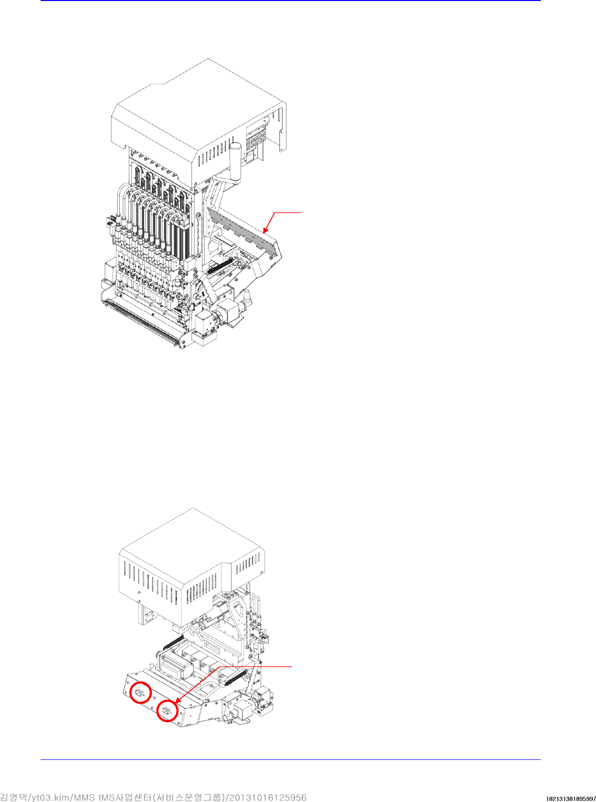
4.2.1.2. Flying IO Board replacement procedure
1. Manipulate the teaching box to move the head module to the front.
2. Close the PC as usual and turn off the main switch at the front of the machine.
3. Remove the connectors connected to the head module.
Flying IO Board
Connector
Head
4-7
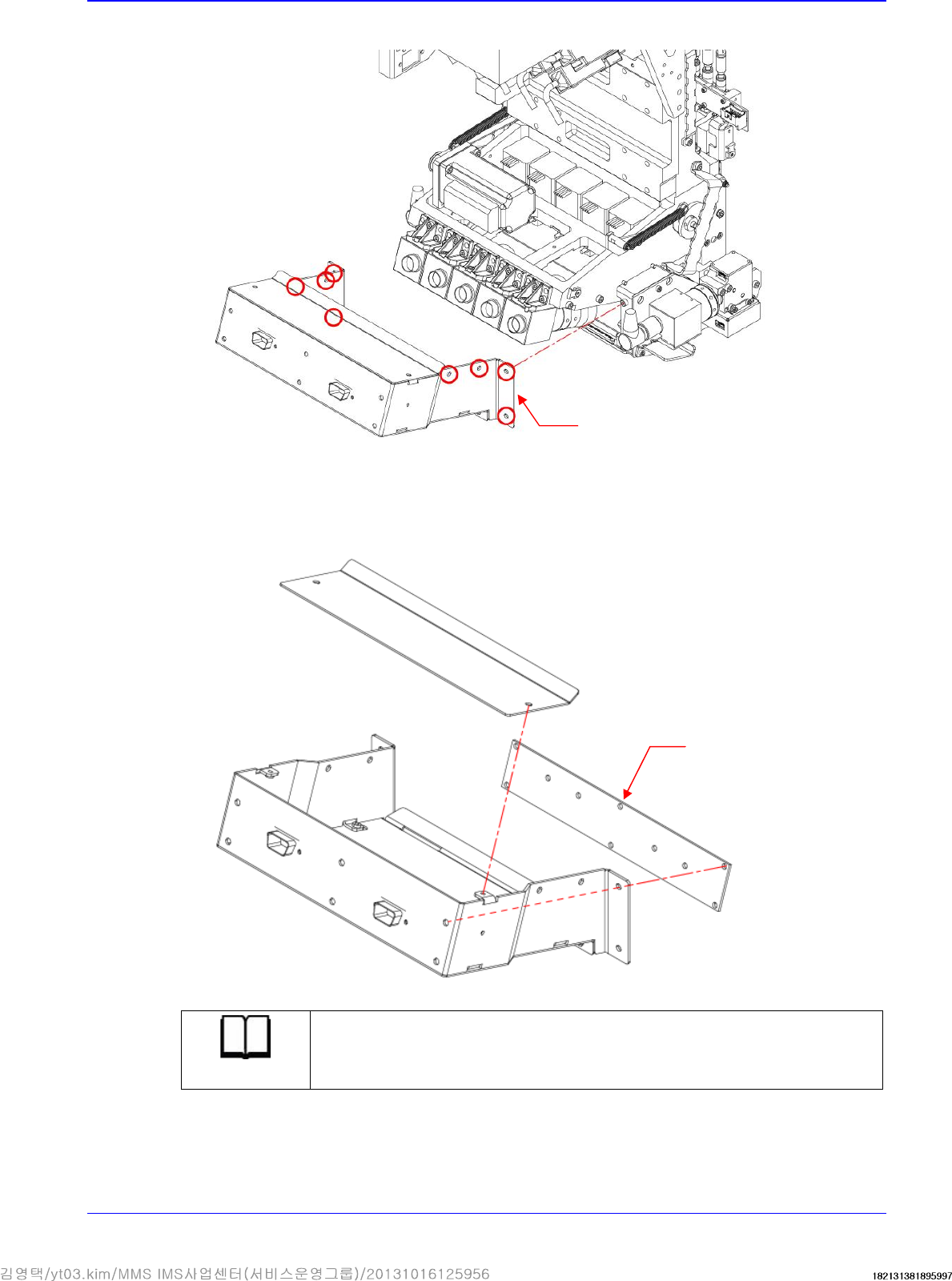
4. Unscrew the fixing bolts securing the Camera Cover using a hex wrench and remove it.
5. Remove the cable connected to board.
6. Remove the board.
7. Replace the board with a new one.
Reference
The part number of the new Flying IO board is AM06-000358A
8. Assemble the board in the reverse order of disassembling.
Camera Cover
Flying IO Board
Advanced High Speed Flexible Mounter
4-8
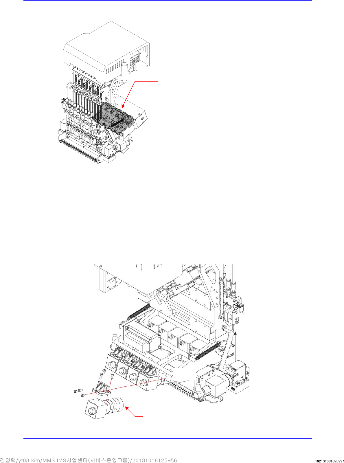
4.2.2. Flying Camera
4.2.2.1. Required tools
T Wrench (other tools supplied) or Hex Wrench
Spanner
4.2.2.2. Flying camera replacement procedure
1. Remove the camera cover referring to the flying IO board removal procedure.
2. Remove the connectors connected to the flying IO board.
3. Remove the connectors connected to camera.
4. Unscrew the fixing bolts securing the Camera using a hex wrench and remove it.
Camera
Flying Camera