04_SM481_Service Manual Head.pdf - 第7页
Head 4-3 Chap ter 4. Head 4.1. Head Module 4.1.1. Require d Tools T W r en ch or He x W r ench 4.1.2. Head Module Re m oval Pro cedure 1. Mani pulate the t eaching box to move t he he a d mod ule t o the front. 2. Clo …

Head
4-3
Chapter 4. Head
4.1. Head Module
4.1.1. Required Tools
T Wrench or Hex Wrench
4.1.2. Head Module Removal Procedure
1. Manipulate the teaching box to move the head module to the front.
2. Close the PC as usual and turn off the main switch at the front of the machine.
3. Cut off the main pneumatic air supply.
4. Remove the pneumatic tube connected to the head module.
5. Remove the connectors connected to the head module.
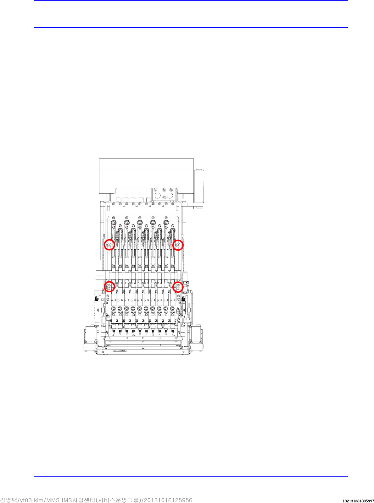
6. Unscrew the fixing bolts as shown in the following figure using a hex wrench.
Advanced High Speed Flexible Mounter
4-4
4.1.3. Head Module Assembling Procedure
1. Assemble the head module in the reverse order of disassembling. However, assemble it paying
attention to the following.
2. Once the assembling is completed, turn on the main switch on the front of the machine and
boot the PC.
3. It is necessary to perform calibration of the following.
Axis Home Calibration
Fiducial Camera Calibration
Gantry Common XY
Gantry Mapping
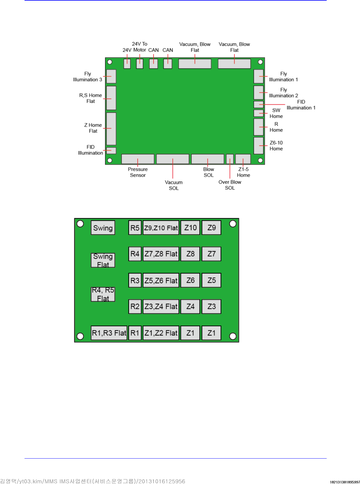
Head IF Board
Motor IF Board