04_SM481_Service Manual Head.pdf - 第19页
Head 4-15 4.2.4. Fl ying I llu m i natio n 4.2.4.1 . Require d too ls T W r en ch (othe r tools supplied ) or He x W r ench 4.2.4.2 . Outer A Boar d replacem ent pr ocedure 1. Mani pulate the t eaching box to move t he…
Advanced High Speed Flexible Mounter
4-14
4. Unscrew the fixing bolts securing the Mirror using a hex wrench and remove it.
5. Replace the Mirror with a new one.
Reference
The part number of the new mirror is EP12-000030A
6. Assemble the mirror in the reverse order of disassembling.
7. Perform Fly-Camera Scale Calibration.
Clamp
Mirror
Bracket
Plate
Head
4-15
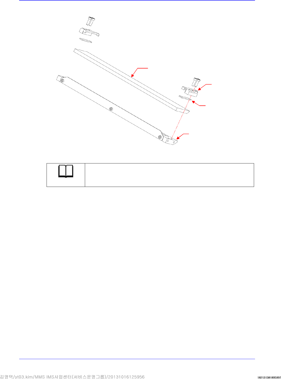
4.2.4. Flying Illumination
4.2.4.1. Required tools
T Wrench (other tools supplied) or Hex Wrench
4.2.4.2. Outer A Board replacement procedure
1. Manipulate the teaching box to move the head module to the front.
2. Close the PC as usual and turn off the main switch at the front of the machine.
3. Remove the cable connected to board.
4. Unscrew the fixing bolts securing the mirror ass'y using a hex wrench and remove it.
Outer A Illumination
Outer B Illumination
Coaxial Illumination
Side Illumination
Outer Bracket
Advanced High Speed Flexible Mounter
4-16
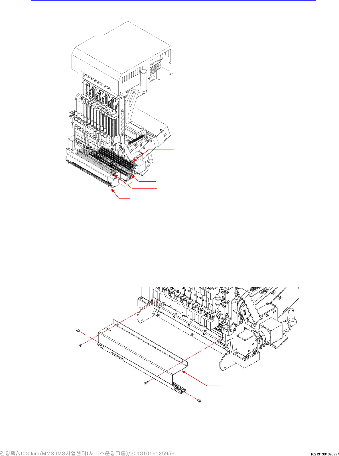
5. Unscrew the fixing bolts securing the board using a hex wrench and remove it.
6. Replace the board with a new one.
Reference
The part number of the new board A is AM03-005090A.
The part number of the new board B is AM03-005089A.
7. Assemble the board in the reverse order of disassembling.
8. Perform light mapping.
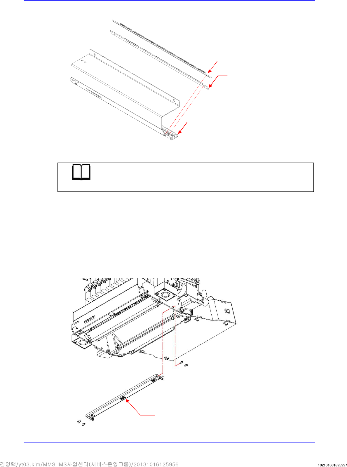
4.2.4.3. Outer B Board replacement procedure
1. Manipulate the teaching box to move the head module to the front.
2. Close the PC as usual and turn off the main switch at the front of the machine.
3. Remove the cable connected to board.
4. Unscrew the fixing bolts securing the Outer Bracket using a hex wrench and remove it.
Board A
Board B
Outer Bracket
Outer Bracket