04_SM481_Service Manual Head.pdf - 第14页
Advance d High Speed Flex i ble Mounter 4-10 9. Perfo r m the following pr oced ur e to move the calibration tool to the ‘ pa rt -ali gnme nt height ’ . Sele ct a part i n the ‘ P ar t ’ di a log b ox and click t he &l…
Head
4-9
5. Replace the camera with a new one.
Reference
The part number of the new camera is J91851018A
6. Assemble the camera in the reverse order of disassembling.
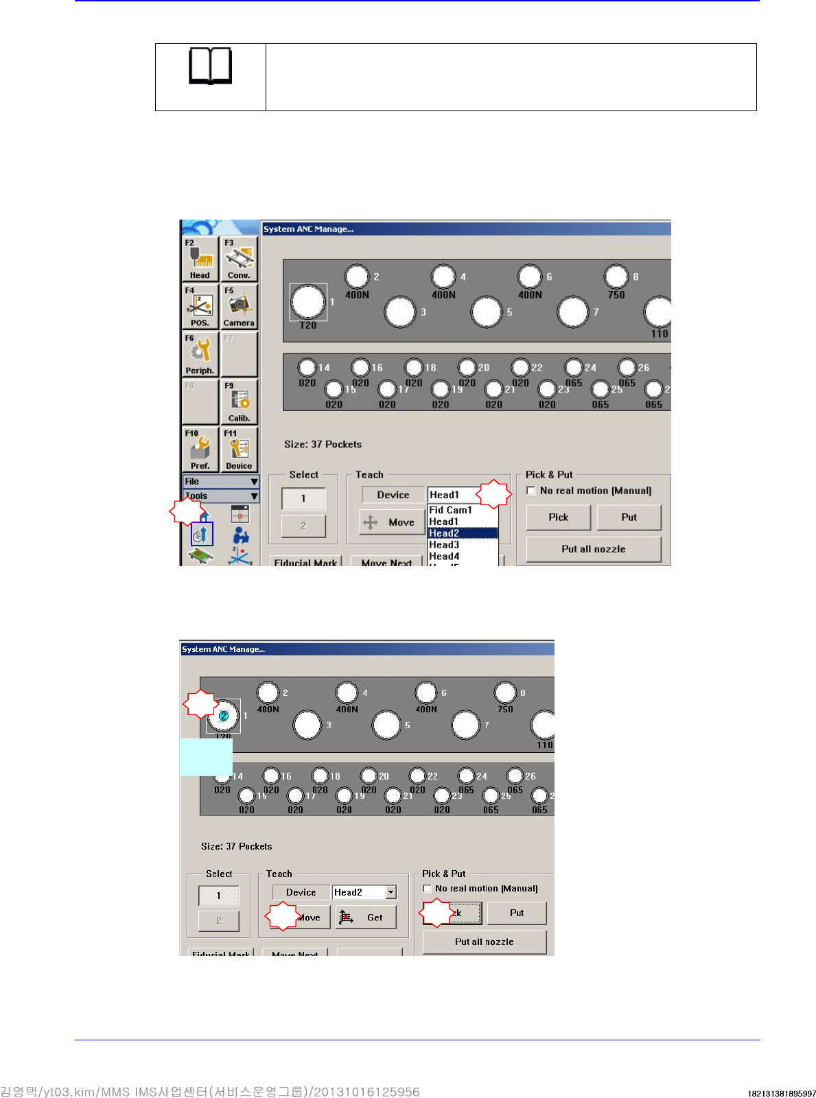
7. Turn on the main switch on the front side of the machine and boot the PC.
8. Insert the calibration tool (CNT20) in the nozzle-hoder of the head corresponding to the
replaced camera.
1
2
Select the head corresponding to the replaced camera
4
3
Select
CNT20
5
Advanced High Speed Flexible Mounter
4-10
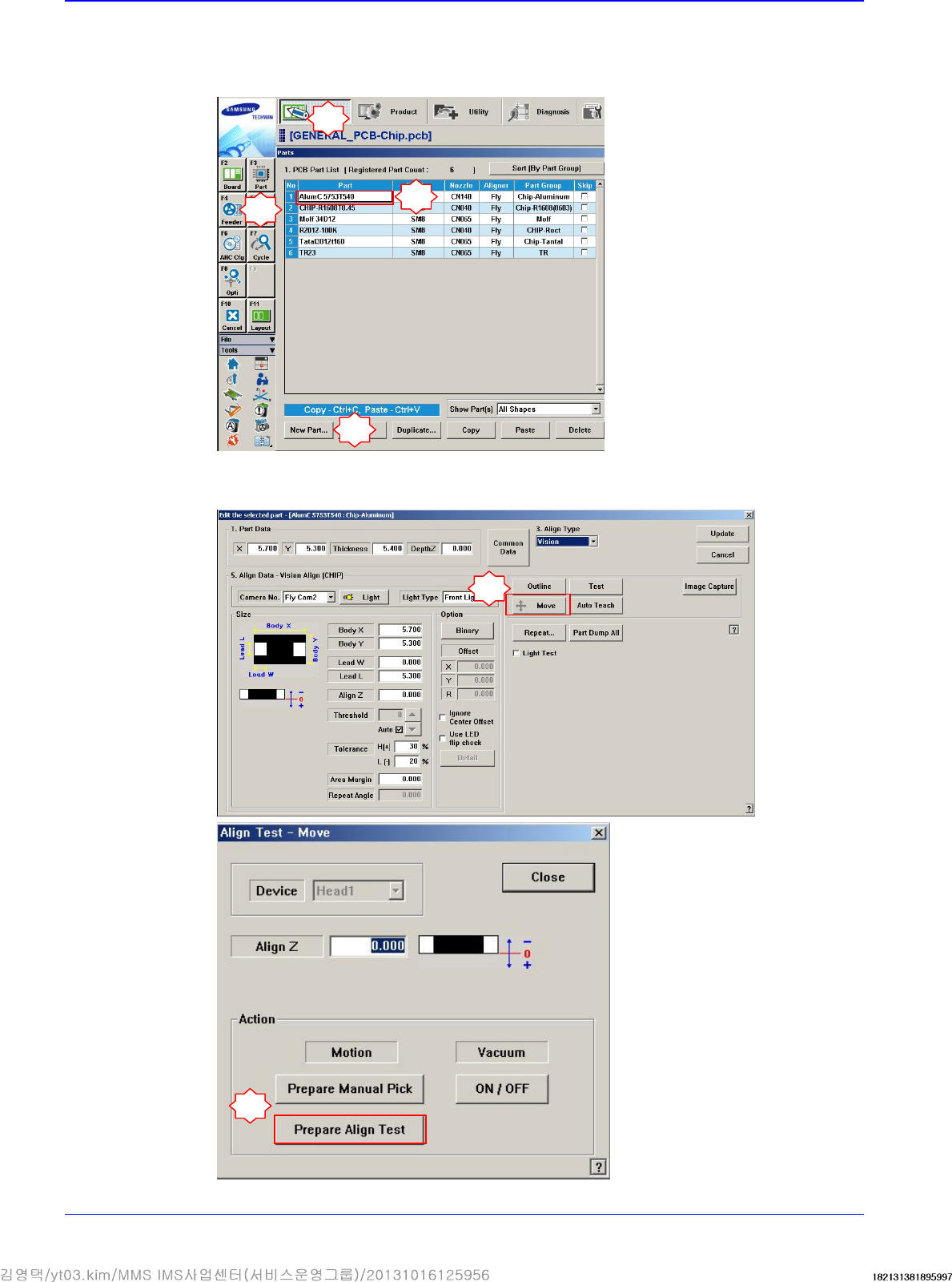
9. Perform the following procedure to move the calibration tool to the ‘part-alignment height’.
Select a part in the ‘Part’ dialog box and click the <Edit> button. Execute the ‘Part Editor’
dialog box.
Click the <Move> button and then click the <Prepare Align Test> button.
1
2
3
5
6
4
Head
4-11
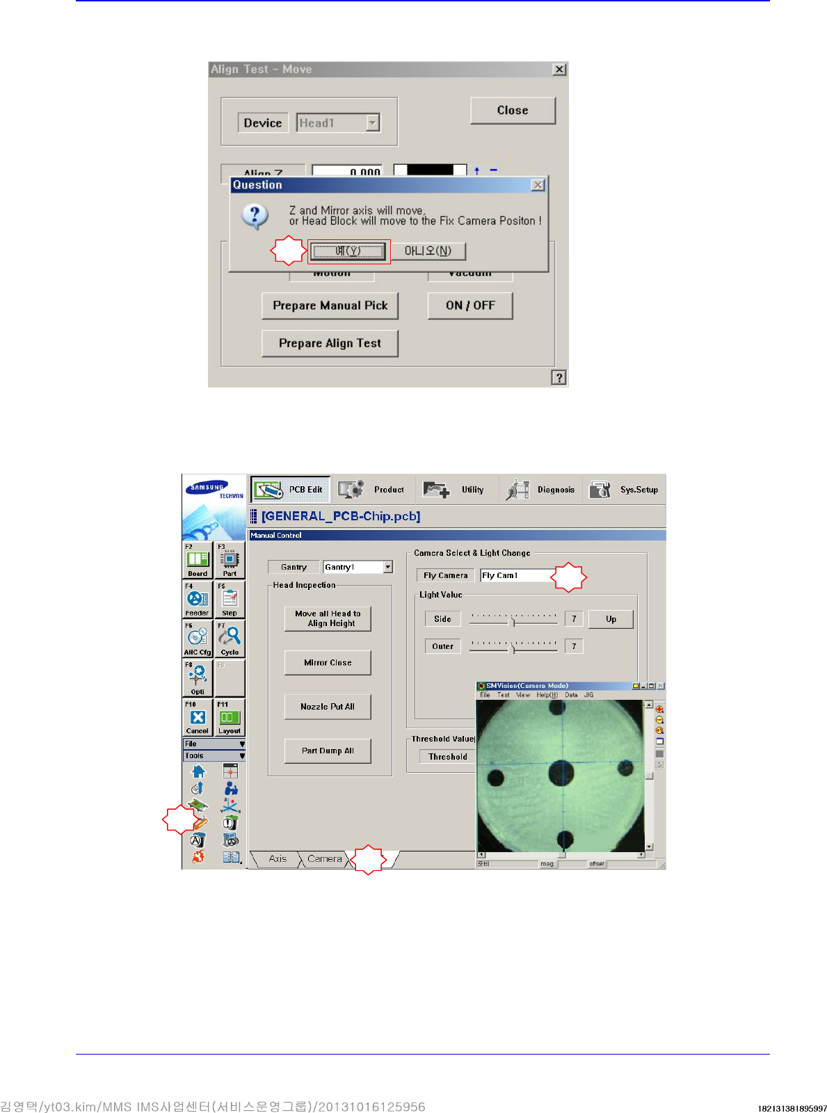
If the message “Z and Mirror axis will move or Head Block will move tothe Fix Camera
Position” is displayed, click the <Yes> button.
Then the Z axis and mirror move to the position for the part-alignment.
10. Execute the ‘Manual Control’ dialog box to select the Head tab screen and select the replaced
Fly-Camera.
7
1
2
3