04_SM481_Service Manual Head.pdf - 第32页
Advance d High Speed Flex i ble Mounter 4-28 Switch9: In/Ou t (HD/VD) OFF ON Switch 10: 75 Ω terminatio n OFF OFF No. Switc h Na me Facto ry-s etti ng STW -setti ng 2 Manual GAIN (M GAIN) contr ol knob Middle Middle Gain…
Head
4-27
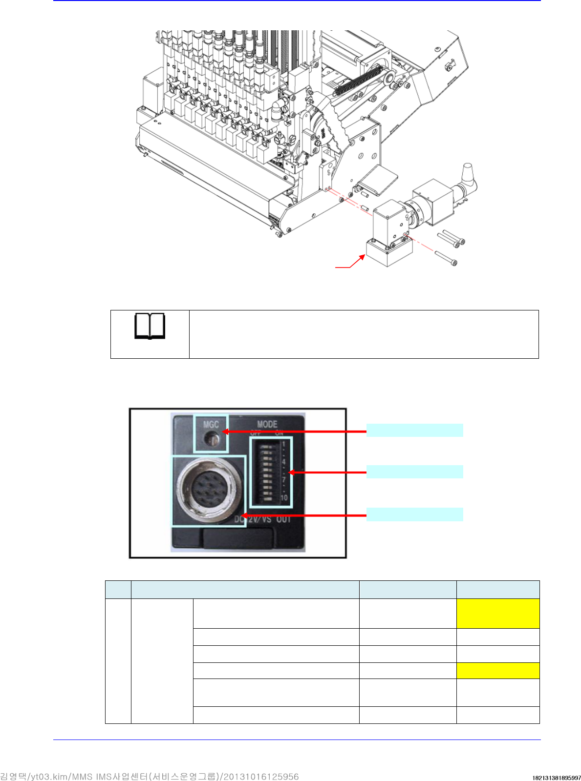
4. Unscrew the fixing bolts securing the fiducial camera nut using a hex wrench and remove it.
5. Replace the fiducial camera with a new one.
Reference
The part number of the new fiducial camera is J91851019A
6. Assemble the camera in the reverse order of disassembling.
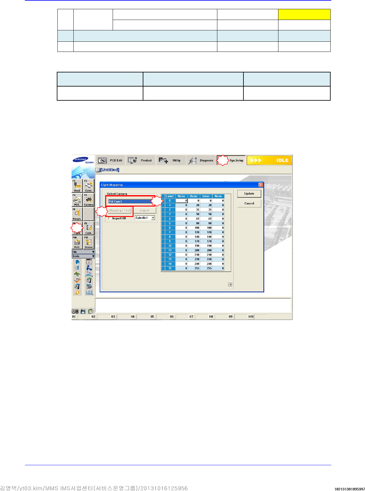
7. Setting camera.
No.
Switch Name Factory-setting STW-setting
1
Shutter
speed/Mode
Switch 1: Shutter speed
* Note 1)
OFF ON
Switch 2: Shutter speed OFF OFF
Switch 3: Shutter speed OFF OFF
Switch 4: FRAME/FIELD
OFF ON
Switch 5-7: Normal/Long
Time/Trigger(Non-Reset, Reset)
OFF
OFF
Switch 8: Double Speed
OFF
OFF
Camera setting swicth
Camera setting swicth
Cable connector
Fiducial Camera
Advanced High Speed Flexible Mounter
4-28
Switch9: In/Out (HD/VD)
OFF
ON
Switch 10: 75Ω termination
OFF OFF
No.
Switch Name Factory-setting STW-setting
2
Manual GAIN (M GAIN) control knob
Middle Middle
Gain Adjustment: CIS G20E20STW Camera
Setup Position Factory-setting STW-setting
Fiducial Camera Middle(Default) 12 o'clock direction
8. If it is deemed necessary to repair the camera, send it to our factory for repair.
9. Turn on the main switch on the front side of the machine and boot the PC once the assembling
is completed. Then, match the horizontal line of the cross hair of the camera so that it may
become parallel to the front fixed conveyor frame while watching the ‘SMVision’ window or
by using a jig.
10. Check whether fiducial camera brightness has been changed.
11. Check for brightness change visually while adjusting the outer and inner lighting values. (Since
it is difficult to directly check the inner lighting value visually, use a mirror to check it.)
12. Check for proper outputs to the Vision window: There must not be any noise, cut screens,
distorted screens and unoutputted images.
13. Set the coordinates of the ANC fiducial marks #1 and #2 and check the fiducial data.
14. It is necessary to perform calibration of the following:
Fiducial Camera Calibration
Gantry Common XY
Gantry Mapping
Conveyor Calibration
Board Position Setup
1
2
3
4

Head
4-29
ANC Position
Fid Camera Offset
Head Offset