04_SM481_Service Manual Head.pdf - 第15页
Head 4-1 1 If the message “ Z and Mirr or axis will move or He a d Bloc k w i ll move tothe Fix Came r a Posi t ion ” is displ ayed, click the <Y e s> button . Then the Z axis and m irror m ove t o the p osi t …
Advanced High Speed Flexible Mounter
4-10
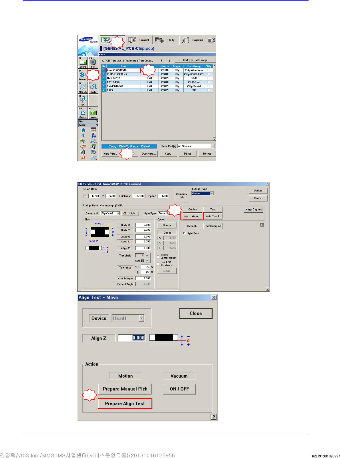
9. Perform the following procedure to move the calibration tool to the ‘part-alignment height’.
Select a part in the ‘Part’ dialog box and click the <Edit> button. Execute the ‘Part Editor’
dialog box.
Click the <Move> button and then click the <Prepare Align Test> button.
1
2
3
5
6
4
Head
4-11
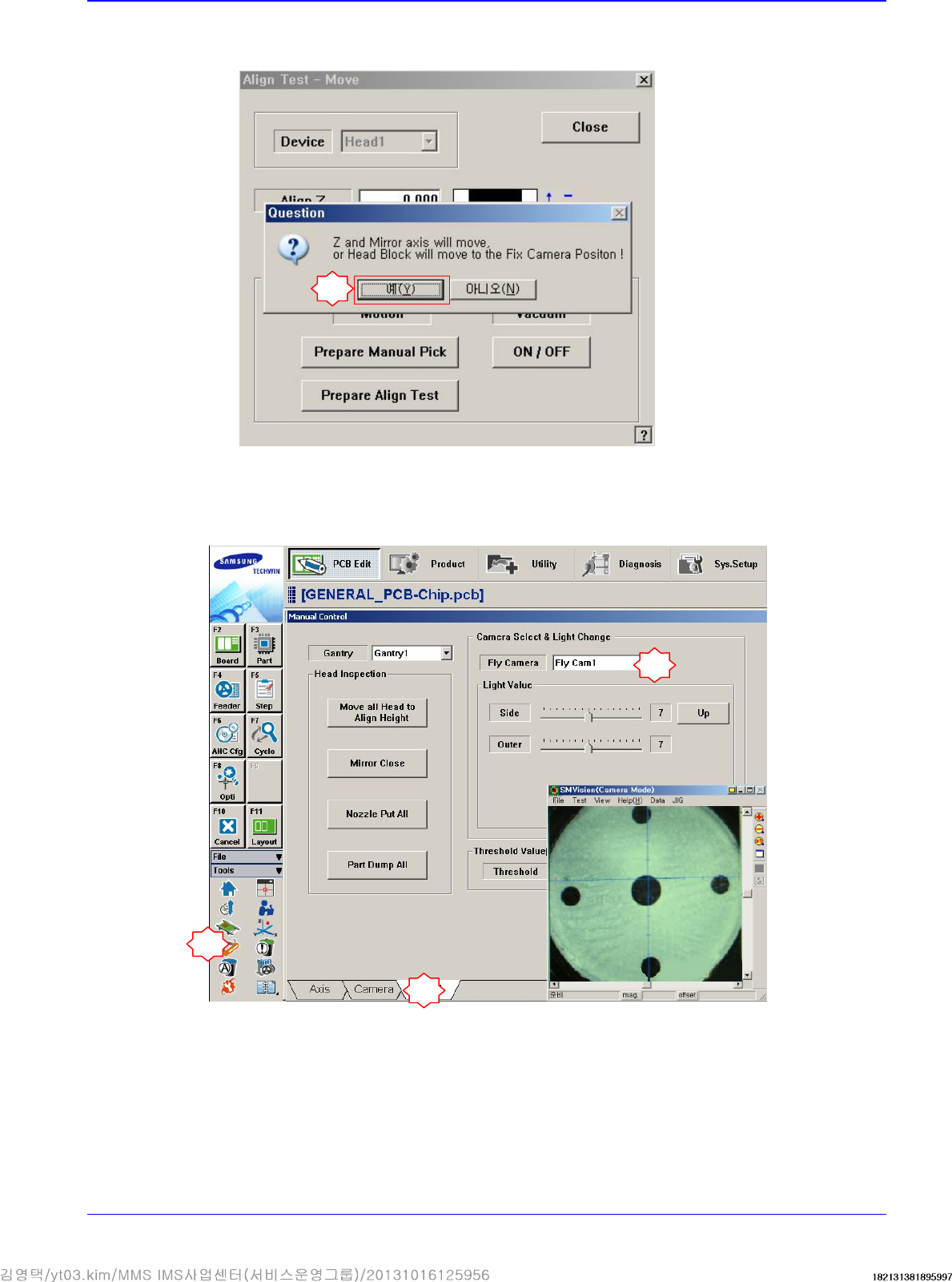
If the message “Z and Mirror axis will move or Head Block will move tothe Fix Camera
Position” is displayed, click the <Yes> button.
Then the Z axis and mirror move to the position for the part-alignment.
10. Execute the ‘Manual Control’ dialog box to select the Head tab screen and select the replaced
Fly-Camera.
7
1
2
3
Advanced High Speed Flexible Mounter
4-12
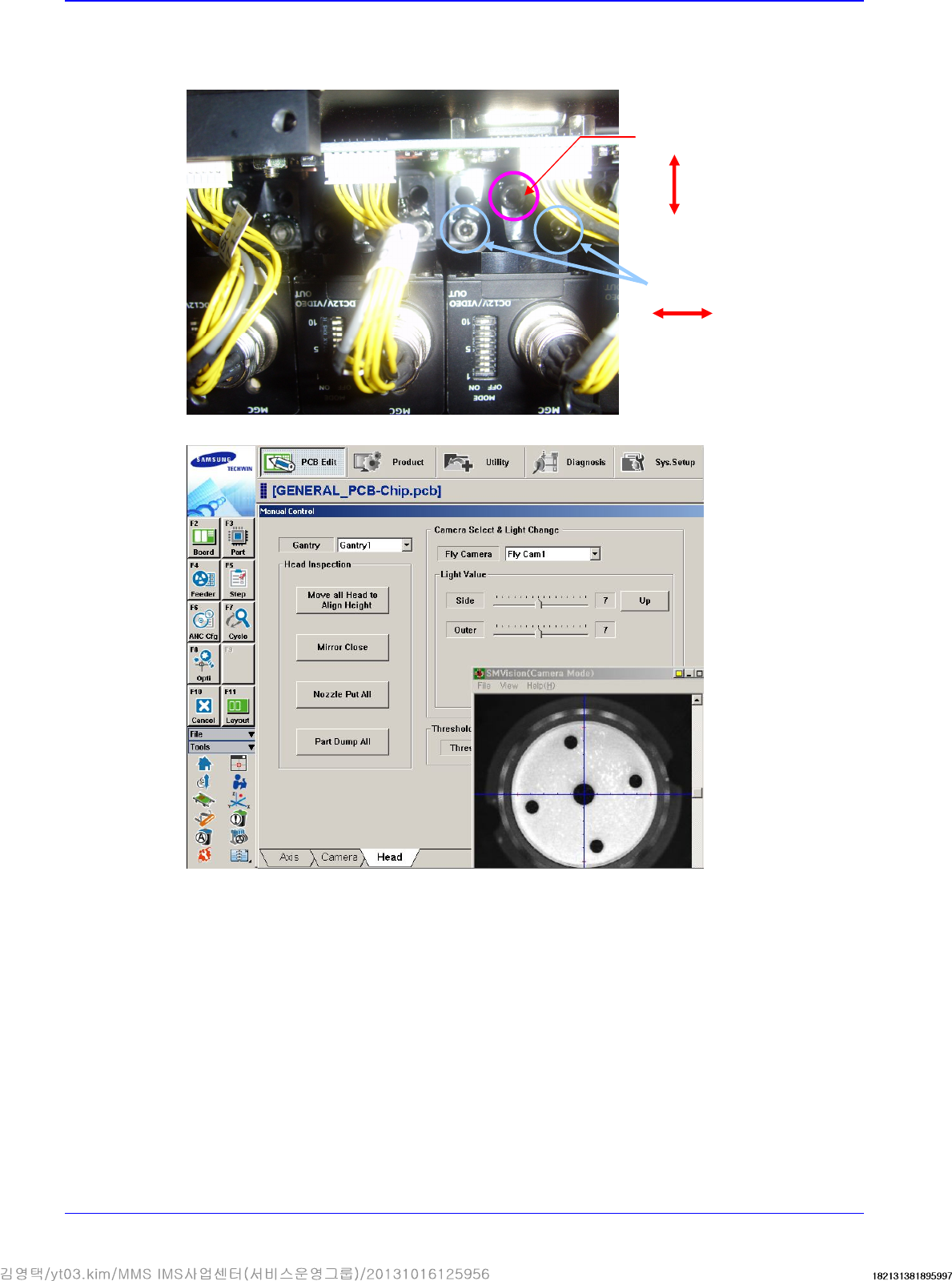
11. Adjust the X and Y coordinates using the fixing screws that fix the camera shown in the
following figure. Adjust 3 fixing screws so that the calibration tool center matches with the
cross hair through the ‘SMVision’ window.
12. Perform the calibration of the ‘Fly camera scale calibration’.
Y direction adjustment
X
direction adjustment