04_SM481_Service Manual Head.pdf - 第23页
Head 4-19 4. Un scr ew the fixing b ol ts securing the board using a he x wren c h and remove it. 5. Re plac e the bo ar d wi t h a new one. Referen ce The part number of t h e new board A is AM03-005087A . 6. A ss em bl…
Advanced High Speed Flexible Mounter
4-18
5. Unscrew the fixing bolts securing the board using a hex wrench and remove it.
6. Replace the board with a new one.
Reference
The part number of the new board A is AM03-005100A.
7. Assemble the board in the reverse order of disassembling.
8. Perform light mapping.
4.2.4.5. Side Illumination replacement procedure
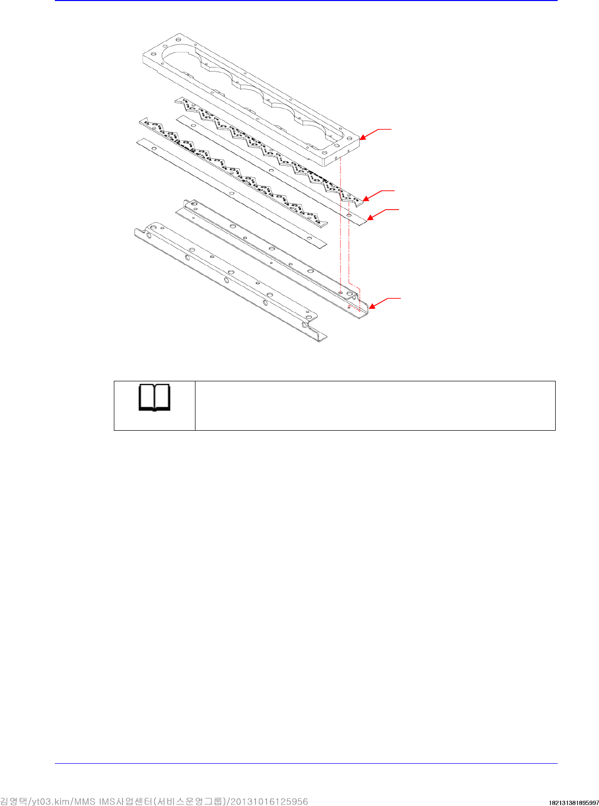
1. Remove the mirror ass'y referring to the mirror removal procedure.
2. Remove the cable connected to board.
3. Unscrew the fixing bolts securing the Side Mirror using a hex wrench and remove it.
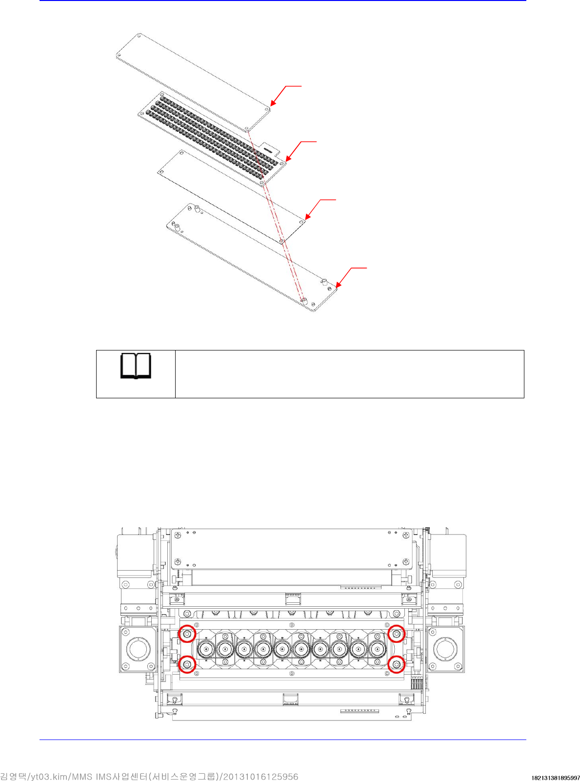
Diffuseer
Coaxial PCB
Plate
Insulation
Head
4-19
4. Unscrew the fixing bolts securing the board using a hex wrench and remove it.
5. Replace the board with a new one.
Reference
The part number of the new board A is AM03-005087A.
6. Assemble the board in the reverse order of disassembling.
7. Perform light mapping.
Side PCB
Plate
Insulation
Bracket
Advanced High Speed Flexible Mounter
4-20
4.3. Ball Spline
4.3.1. Required tools
T Wrench (other tools supplied) or Hex Wrench
Spanner
Tool or jig for concentricity measurement
4.3.2. Ball spline replacement procedure
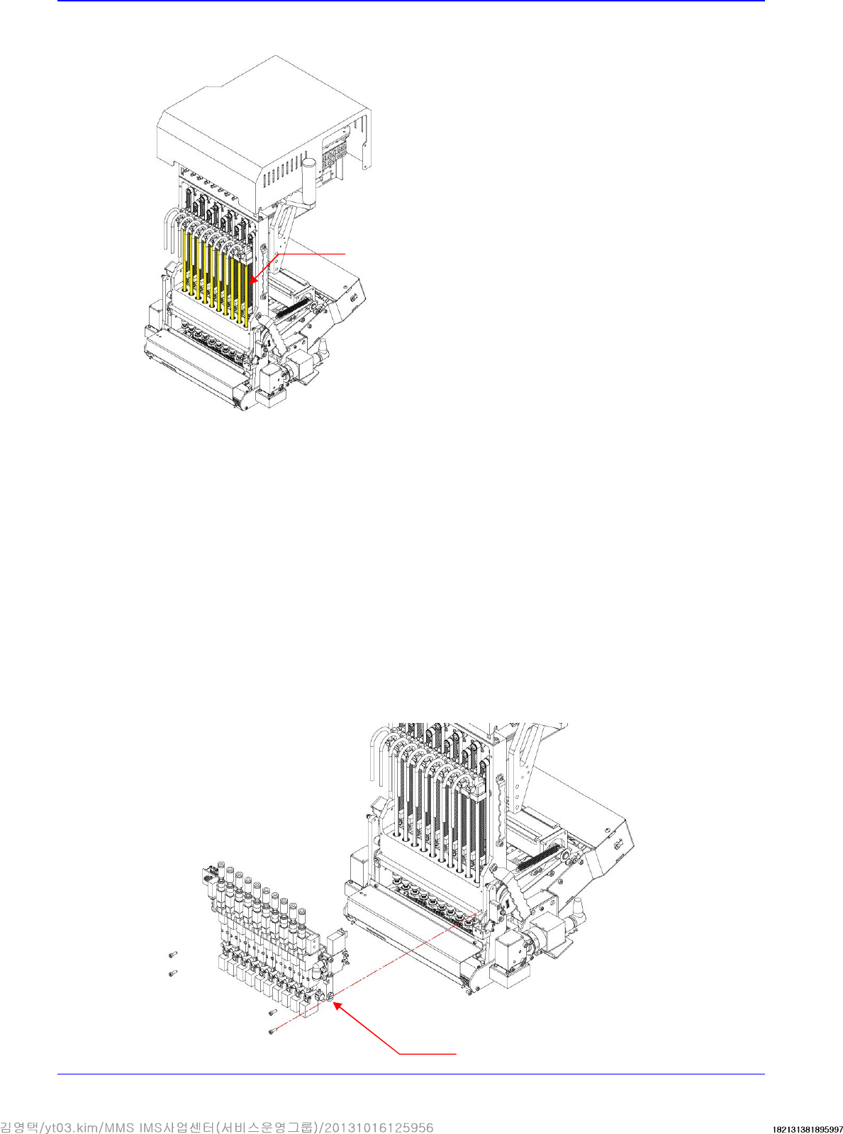
1. Manipulate the teaching box to move the head module to the front.
2. Close the PC as usual and turn off the main switch at the front of the machine.
3. Cut off the main pneumatic air supply.
4. Remove the pneumatic tube connected to the head module.
5. Remove the connectors connected to the spindle ass'y.
6. Unscrew the fixing bolts securing the air module ass'y using a hex wrench and remove it.
Ball Spline
Air Module