04_SM481_Service Manual Head.pdf - 第16页
Advance d High Speed Flex i ble Mounter 4-12 11. Adjust the X and Y c oordinates using the f ixing screws that fix the ca me ra shown in th e follow ing figure. Adjust 3 fi xing screw s so that the ca li br a tion tool c…
Head
4-11
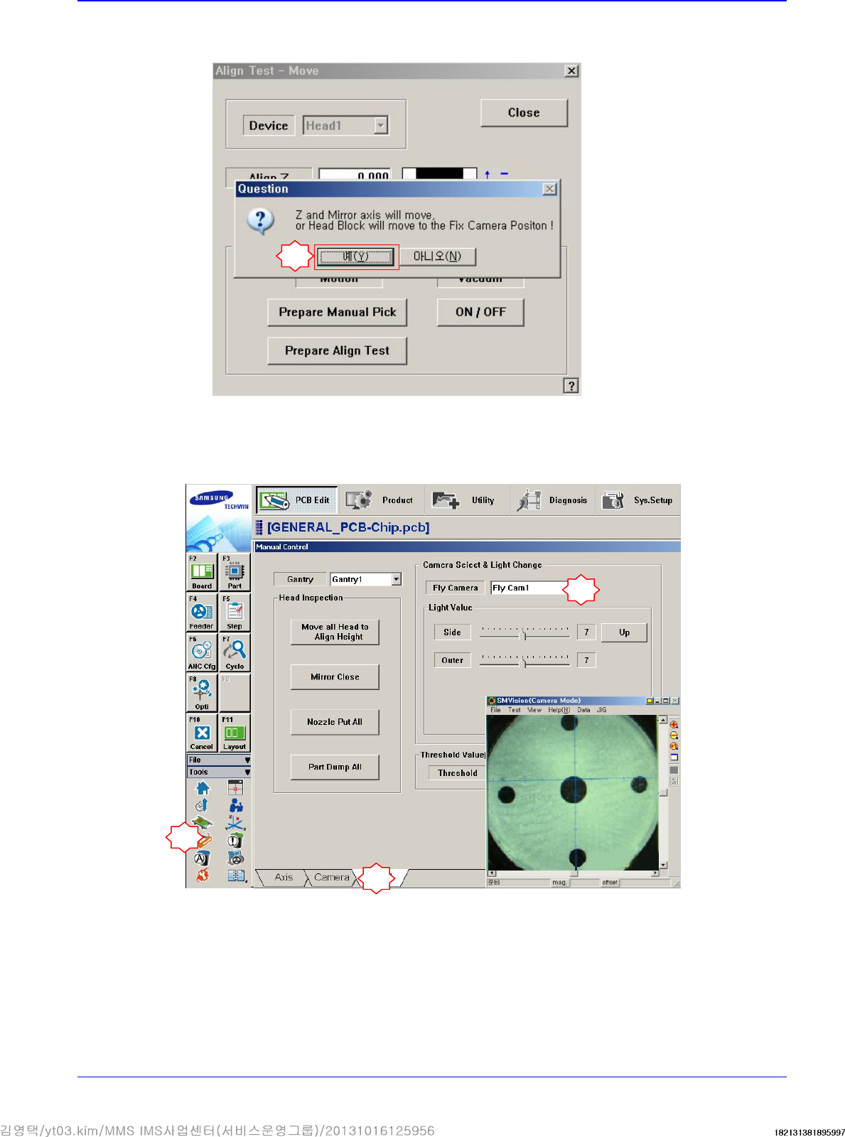
If the message “Z and Mirror axis will move or Head Block will move tothe Fix Camera
Position” is displayed, click the <Yes> button.
Then the Z axis and mirror move to the position for the part-alignment.
10. Execute the ‘Manual Control’ dialog box to select the Head tab screen and select the replaced
Fly-Camera.
7
1
2
3
Advanced High Speed Flexible Mounter
4-12
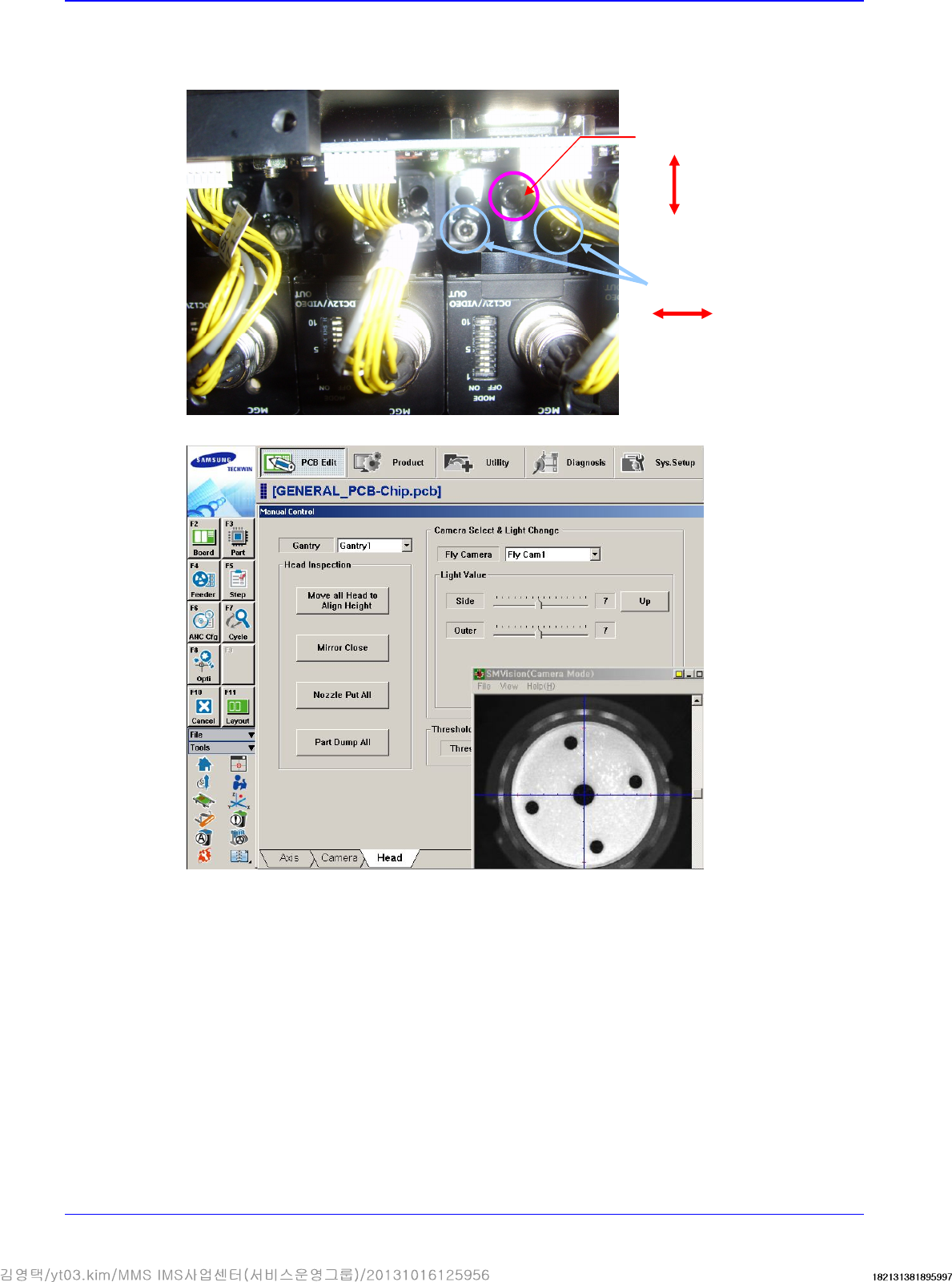
11. Adjust the X and Y coordinates using the fixing screws that fix the camera shown in the
following figure. Adjust 3 fixing screws so that the calibration tool center matches with the
cross hair through the ‘SMVision’ window.
12. Perform the calibration of the ‘Fly camera scale calibration’.
Y direction adjustment
X
direction adjustment
Head
4-13
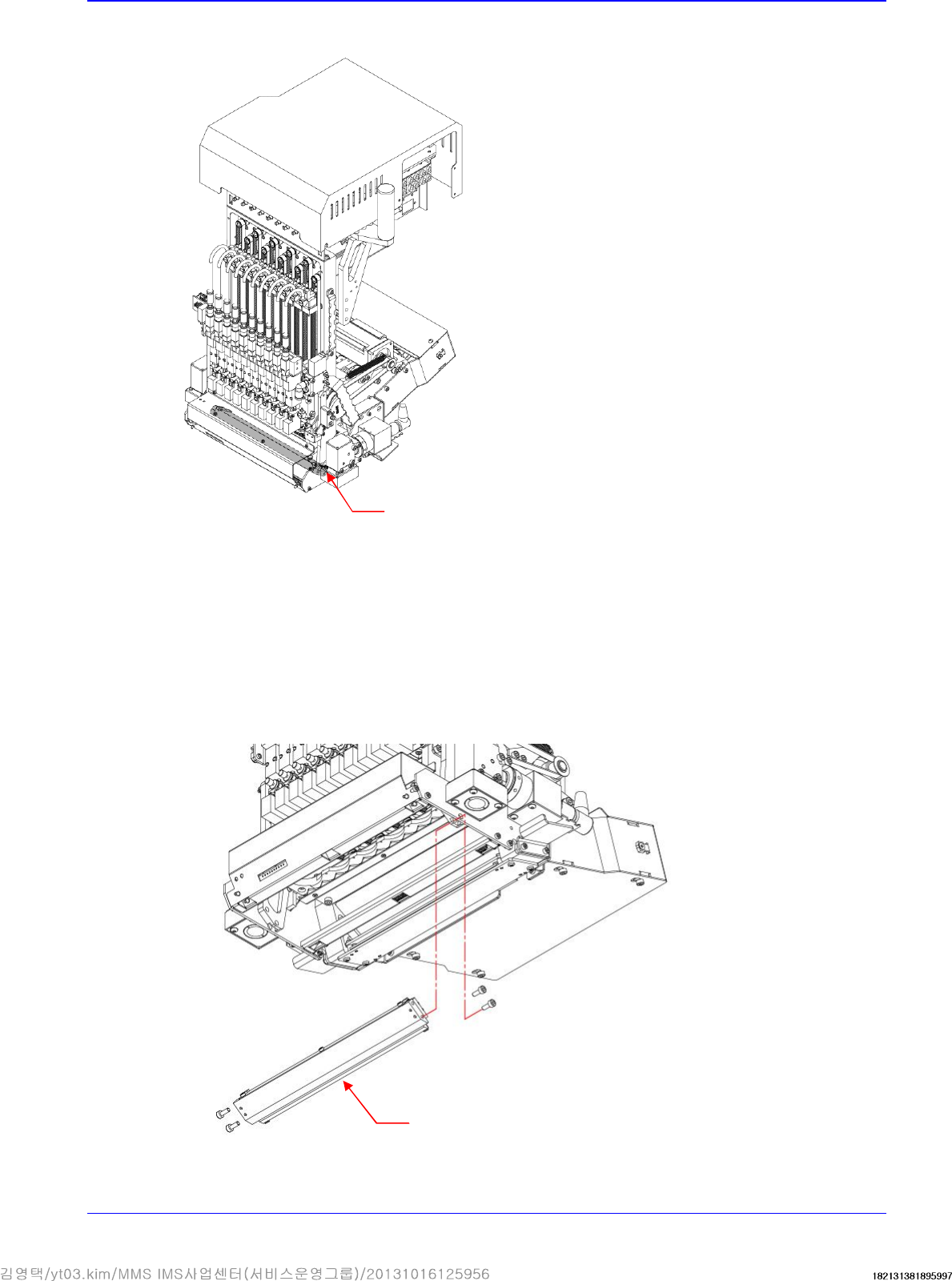
4.2.3. Flying Mirror
4.2.3.1. Required tools
T Wrench (other tools supplied) or Hex Wrench
4.2.3.2. Flying Mirror replacement procedure
1. Manipulate the teaching box to move the head module to the front.
2. Close the PC as usual and turn off the main switch at the front of the machine.
3. Unscrew the fixing bolts securing the Mirror Ass'y using a hex wrench and remove it.
Flying Mirror
Mirror Ass'y