04_SM481_Service Manual Head.pdf - 第6页
在线预览 04_SM481_Service Manual Head.pdf PDF 文档。

Table of Contents
4-1
Table of Contents
Main Contents
Table of Contents ................................................................................................ 4-1
Main Contents ................................................................................................ 4-1
Chapter 4. Head ................................................................................................ 4-3
4.1. Head Module .......................................................................................... 4-3
4.1.1. Required Tools ....................................................................................... 4-3
4.1.2. Head Module Removal Procedure .......................................................... 4-3
4.1.3. Head Module Assembling Procedure ...................................................... 4-4
4.2. Flying Vision ........................................................................................... 4-6
4.2.1. Flying IO Board ....................................................................................... 4-6
4.2.2. Flying Camera ........................................................................................ 4-8
4.2.3. Flying Mirror ......................................................................................... 4-13
4.2.4. Flying Illumination ................................................................................. 4-15
4.3. Ball Spline ............................................................................................ 4-20
4.3.1. Required tools ...................................................................................... 4-20
4.3.2. Ball spline replacement procedure ........................................................ 4-20
4.4. Spindle Housing ................................................................................... 4-24
4.4.1. Required tools ...................................................................................... 4-24
4.4.2. Spindle Housing replacement procedure .............................................. 4-24
4.5. Fiducial Camera ................................................................................... 4-26
4.5.1. Required tools ...................................................................................... 4-26
4.5.2. Fiducial replacement procedure ............................................................ 4-26
4.6. Swing Motor / Swing Timing Belt.......................................................... 4-30
4.6.1. Required tools ...................................................................................... 4-30
4.6.2. Motor replacement procedure ............................................................... 4-30
4.6.3. Belt replacement procedure .................................................................. 4-32
4.7. R-Axis Motor / Timing belt .................................................................... 4-33
4.7.1. Required tools ...................................................................................... 4-33
4.7.2. R-Axis Motor/Timing belt/Sensor replacement procedure ..................... 4-33
4.8. Z-Axis Motor / Timing belt .................................................................... 4-38
4.8.1. Required tools ...................................................................................... 4-38
4.8.2. Z-Axis Motor / Timing belt replacement procedure ................................ 4-38

Head
4-3
Chapter 4. Head
4.1. Head Module
4.1.1. Required Tools
T Wrench or Hex Wrench
4.1.2. Head Module Removal Procedure
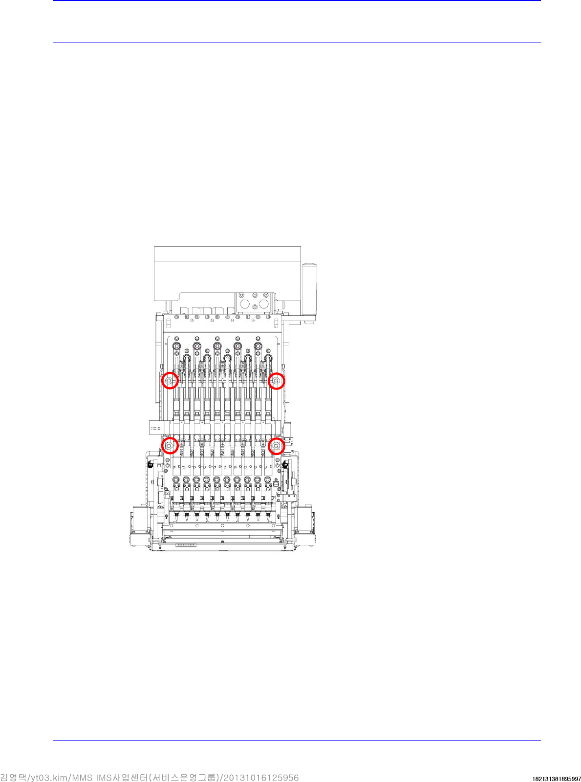
1. Manipulate the teaching box to move the head module to the front.
2. Close the PC as usual and turn off the main switch at the front of the machine.
3. Cut off the main pneumatic air supply.
4. Remove the pneumatic tube connected to the head module.
5. Remove the connectors connected to the head module.
6. Unscrew the fixing bolts as shown in the following figure using a hex wrench.