00197490-03_SM_CP20-P-M2_EN保养维护.pdf - 第19页
3 Usability package 3.2 Fitting the usability kit for SIPLACE C&P20P Service Manual SIPLACE SpeedStar (C&P20 P / C&P20 M2) 03/2018 19 Fig.9: Replacing the handle 2 ► Fit the new handle with three fillister …
3 Usability package
3.2 Fitting the usability kit for SIPLACE C&P20P
18 Service Manual SIPLACE SpeedStar (C&P20 P / C&P20 M2) 03/2018
3.2 Fitting the usability kit for SIPLACE C&P20P
Preparation
► Remove the head from the machine. For details about removing and fitting the placement
head, refer to the service manual for your machine.
Fit the head on the head mount [03056231‑xx].
► Make sure that the component sensor protective cap is fitted.
1.1.3 "Safety instructions for the component sensor" [}6]
Conversion
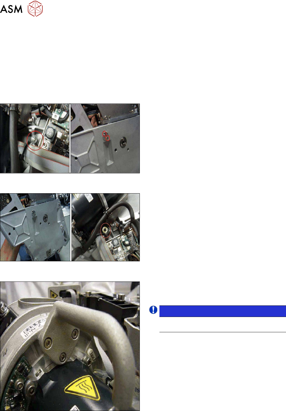
Fig.6: Replacing the safety element 1 (head front and back
sides)
► Remove the old safety element at the top right.
Fig.7: Replacing the safety element 2 (head front and back
sides)
► Fit the new "safety element RO SIPLACE
C&P20P2" [03139206‑xx] with two screws
(ISO4762-M1.6x6‑A2‑70), in place of the old
safety element.
Fig.8: Replacing the handle 1
► Dismantle the old handle. To do this, remove the
three hexagon socket fillister head screws
ISO4762M3x12
NOTICE!
The old screws can be reused for the new
handle.
.
3 Usability package
3.2 Fitting the usability kit for SIPLACE C&P20P
Service Manual SIPLACE SpeedStar (C&P20 P / C&P20 M2) 03/2018 19
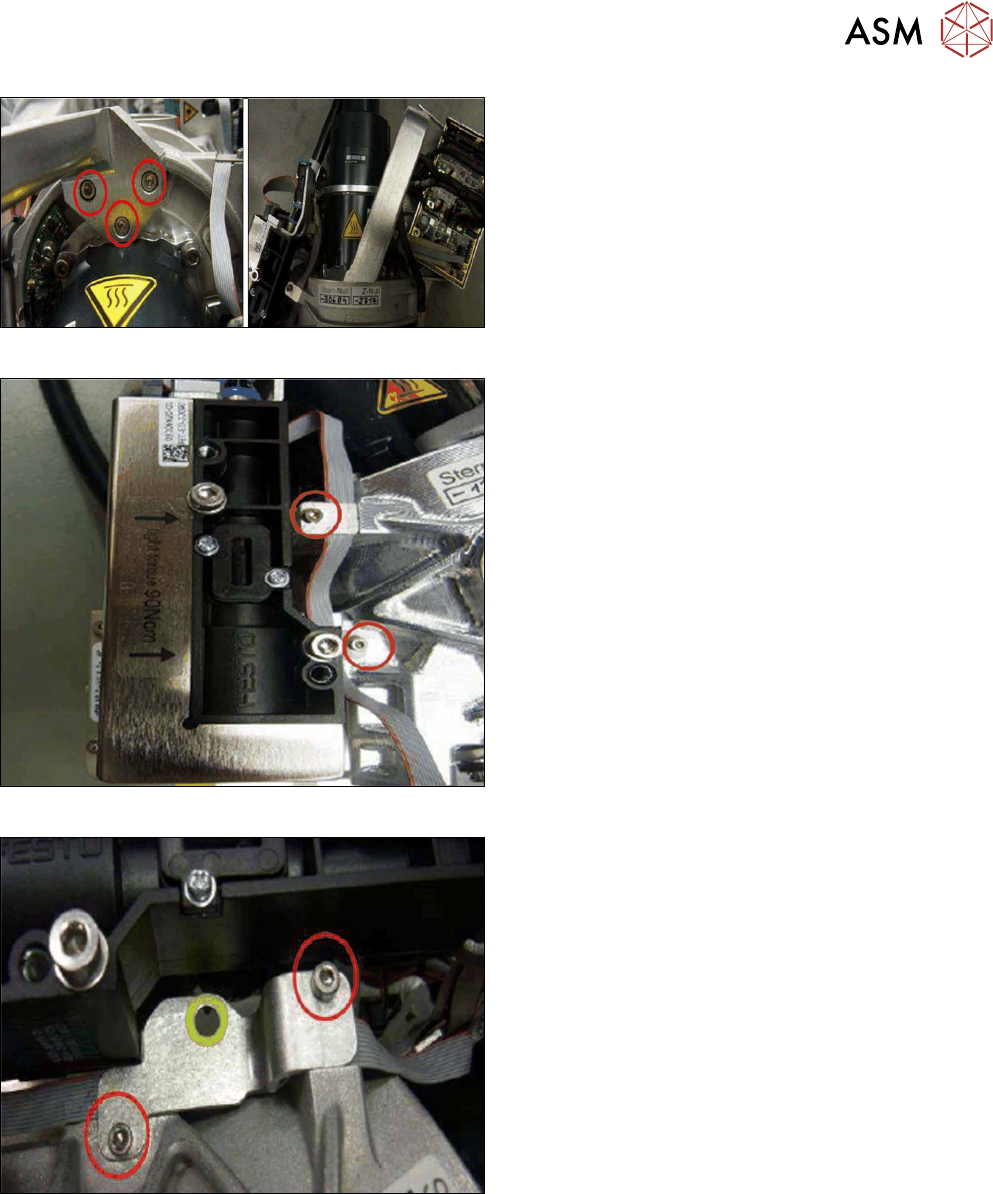
Fig.9: Replacing the handle 2
► Fit the new handle with three fillister head screws
(hexagon socket cap ISO4762M3x12) to the
head carrier.
Fig.10: Replacing the clamping plates 1
► Remove the old clamping plates.
Fig.11: Replacing the clamping plates 2
► Fit the new clamping plate to the head carrier
with two fillister head screws (hexagon socket
cap ISO4762M2.5x6).
3 Usability package
3.2 Fitting the usability kit for SIPLACE C&P20P
20 Service Manual SIPLACE SpeedStar (C&P20 P / C&P20 M2) 03/2018
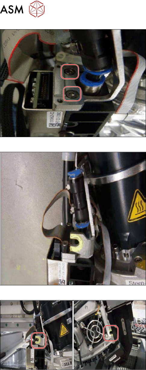
Fig.12: Replacing the holding plate 1
► Dismantle the old holding plate FHE.
Fig.13: Replacing the holding plate 2
► Fasten the new holding plate into place with two
screws (ISO4762-M2.5x8‑A2‑70).
Fig.14: Attaching markings 1
► Attach the two U-shaped markings as shown in
the diagram.
First clean the surface with a lint-free cloth,
moistened with ethanol.