00197490-03_SM_CP20-P-M2_EN保养维护.pdf - 第25页
4 Component camera, Z axis and component sensor 4.1 Replacing the component camera Service Manual SIPLACE SpeedStar (C&P20 P / C&P20 M2) 03/2018 25 4 Component camera, Z axis and component sensor 4.1 Replacing th…

3 Usability package
3.2 Fitting the usability kit for SIPLACE C&P20P
24 Service Manual SIPLACE SpeedStar (C&P20 P / C&P20 M2) 03/2018
4 Component camera, Z axis and component sensor
4.1 Replacing the component camera
Service Manual SIPLACE SpeedStar (C&P20 P / C&P20 M2) 03/2018 25
4 Component camera, Z axis and component
sensor
4.1 Replacing the component camera
Parts
●
Select the required spare part:
– Component camera C&P (type 41) 6x6 GigE C-MOS [03116633Sxx]
– Component camera C&P (type 23) 6x6 GigE [03105195Sxx]
– Component camera C&P (type 41) 6x6 digital RK [03078957Sxx]
– Component camera C&P (type 23) 6x6 digital RK [03003426Sxx]
– For information about other cameras, please refer to the catalog of parts
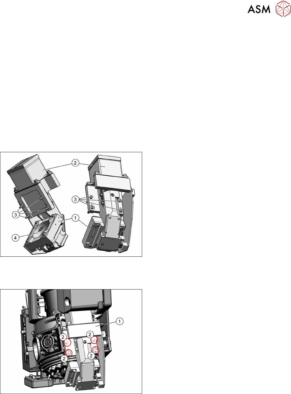
Overview
Fig.21: Component camera (example of type 41 6x6 digital RK
shown [03078957‑xx])
1. Component camera
2. Camera amplifier CCD
3. Four fastening screws for the camera on the
head housing
ISO4762-M3x16-A2-70 [03042545‑xx]
4. Camera lens system
For further information about the repairs needed, refer
to section 4.1.1 "Board: LED driver BE VHS" [}28].
Torque
Fig.22: Screws fastening the component camera
1. Component camera
2. Four fastening screws for the component camera
torque: 1.3Nm
4 Component camera, Z axis and component sensor
4.1 Replacing the component camera
26 Service Manual SIPLACE SpeedStar (C&P20 P / C&P20 M2) 03/2018
Preparation
► Remove the head from the machine. For details about removing and fitting the placement
head, refer to the service manual for your machine.
Fit the head on the head mount [03056231‑xx].
CAUTION
Do not damage or contaminate the camera lens system.
► Make sure that you do not damage or contaminate the camera lens system.
► Make sure that the component sensor protective cap is fitted.
1.1.3 "Safety instructions for the component sensor" [}6]
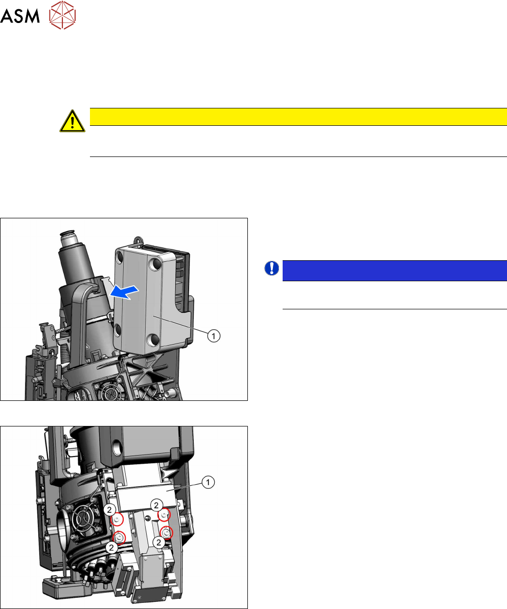
Removal
Fig.23: Pulling the cover off
► Pull the cover(1) off the intermediate distributor.
The cover is fixed by four press studs on the stay
bolts.
NOTICE!
Older heads may not have this cover yet.
.
Fig.24: Screws fastening the component camera
► Unplug all electrical connections from the compo-
nent camera.
► Remove the four screws(2) fastening the compo-
nent camera(1).
► Carefully pull the component camera off the loc-
ating pins.