00197490-03_SM_CP20-P-M2_EN保养维护.pdf - 第75页
8 Return unit and return cylinder 8.3 Replacing the driver lever Service Manual SIPLACE SpeedStar (C&P20 P / C&P20 M2) 03/2018 75 8.3 Replacing the driver lever Parts ● Driver lever [03007700-xx] Overview Fig.11…
8 Return unit and return cylinder
8.2 Replacing the return cylinder or return cylinder holder
74 Service Manual SIPLACE SpeedStar (C&P20 P / C&P20 M2) 03/2018
8.2 Replacing the return cylinder or return cylinder holder
Parts
●
Return cylinder [03007696-xx] or
Holder [03007695-xx]
Overview
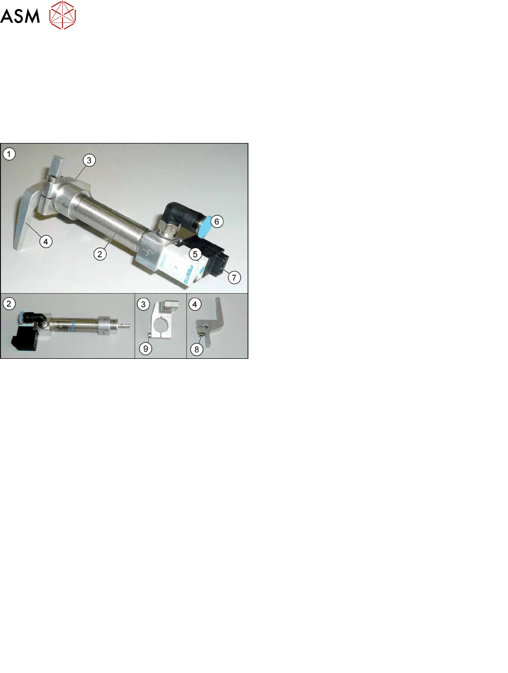
Fig.115: Overview of return unit
1. Return unit assembly
2. Return cylinder
3. Return cylinder holder
4. Driver lever
5. Solenoid valve
6. Compressed air connection
7. Electrical connection
8. Fastening screw for driver lever (4)
9. Fastening screw for "return cylinder holder"(3)
Preparation
► Remove the head from the machine. For details about removing and fitting the placement
head, refer to the service manual for your machine.
Fit the head on the head mount [03056231‑xx].
► Make sure that the component sensor protective cap is fitted.
1.1.3 "Safety instructions for the component sensor" [}6]
Removal
► Dismantle the return unit.
8.1 "Replacing the return unit" [}71]
► Remove the screw fastening the driver lever.
► Remove the screw fastening the "return cylinder holder".
Installation
► Fit the "return cylinder holder" and the driver lever.
Make sure that the return cylinder, the holder and the driver lever are all parallel. You may
need to place the return unit down on a level surface.
► Follow the removal instructions in reverse order for further installation.
Also observe the installation instructions in the following section:
8.1 "Replacing the return unit" [}71]
► Observe in particular the torques specified!
8 Return unit and return cylinder
8.3 Replacing the driver lever
Service Manual SIPLACE SpeedStar (C&P20 P / C&P20 M2) 03/2018 75
8.3 Replacing the driver lever
Parts
●
Driver lever [03007700-xx]
Overview
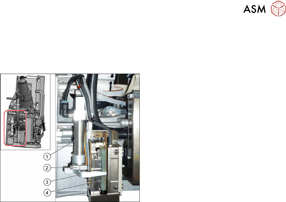
Fig.116: Overview of return unit on the head
1. Return cylinder
2. Return cylinder holder
3. Driver lever for Z axis
4. Rotor on Z motor
The return unit is installed on the Z axis and is re-
sponsible for protecting the Z axis from damage, by
moving it into a safe area in the case of unexpected
events (e.g. power cuts or machine shutdown).
Preparation
► Remove the head from the machine. For details about removing and fitting the placement
head, refer to the service manual for your machine.
Fit the head on the head mount [03056231‑xx].
► Make sure that the component sensor protective cap is fitted.
1.1.3 "Safety instructions for the component sensor" [}6]
Removal
► The return unit does not need to be dismantled when you replace the driver lever. However,
you might find it useful to do so for better access.
8.1 "Replacing the return unit" [}71]
► Remove the screw fastening the driver lever.
8 Return unit and return cylinder
8.3 Replacing the driver lever
76 Service Manual SIPLACE SpeedStar (C&P20 P / C&P20 M2) 03/2018
Installation
► Fit the driver lever fully onto the return cylinder pin and then tighten the fastening screw with a
torque of 1.15 Nm.
Make sure that the return cylinder, the holder and the driver lever are all parallel.
► If you dismantled the return unit, continue with further installation as described there (see 8.1
"Replacing the return unit" [}71]).
If not, perform the following steps:
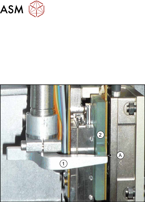
Fig.117: Inspection checks
► Perform the following checks:
●
The driver lever must lie against the Z axis.
●
Check that the star can be revolved.
●
Check the distance(A) between the driver
lever(1) and the rotor(2) of the Z motor. The dis-
tance should be approx. 0.5 mm when the Z axis
is pushed upwards.
► If there are any problems, go through the afore-
mentioned steps again.
► Follow the removal instructions in reverse order for further installation.