00197490-03_SM_CP20-P-M2_EN保养维护.pdf - 第57页
6 Pressure control valve (PRV) 6.2 Replacing the membrane and other small parts on the PRV Service Manual SIPLACE SpeedStar (C&P20 P / C&P20 M2) 03/2018 57 Fig.85: Inserting the O-ring ► Lightly grease the O-rin…
6 Pressure control valve (PRV)
6.2 Replacing the membrane and other small parts on the PRV
56 Service Manual SIPLACE SpeedStar (C&P20 P / C&P20 M2) 03/2018
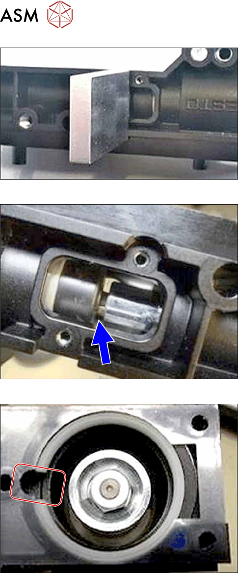
Fig.82: Tool
► Use the tool to make sure that the plunger en-
gages with the membrane.
Fig.83: Checking the membrane
► The membrane must lie on the valve plunger so
that the end of the valve plunger can be seen, as
in the diagram.
► Move the plunger back and forth to check for
ease of movement.
.
Fig.84: Inserting the plastic ring
► Make sure that the opening of the ring is level
with the groove.
6 Pressure control valve (PRV)
6.2 Replacing the membrane and other small parts on the PRV
Service Manual SIPLACE SpeedStar (C&P20 P / C&P20 M2) 03/2018 57
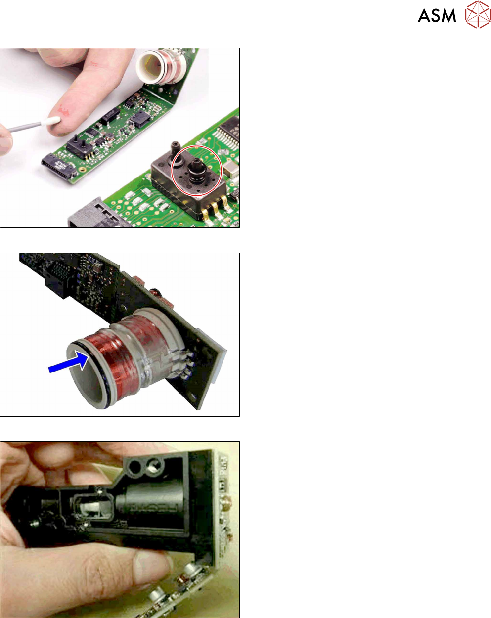
Fig.85: Inserting the O-ring
► Lightly grease the O-ring with a lint-free cotton
swab and "Isoflex Topas 5051" [03078517‑xx].
► Then place the O-ring onto the vacuum sensor.
Fig.86: Greasing the O-ring
► Grease the O-ring slightly with a lint-free cotton
swab and "Isoflex Topas 5051" [03078517‑xx].
Fig.87: Inserting the board
► Push the board and coil into the housing.
6 Pressure control valve (PRV)
6.2 Replacing the membrane and other small parts on the PRV
58 Service Manual SIPLACE SpeedStar (C&P20 P / C&P20 M2) 03/2018
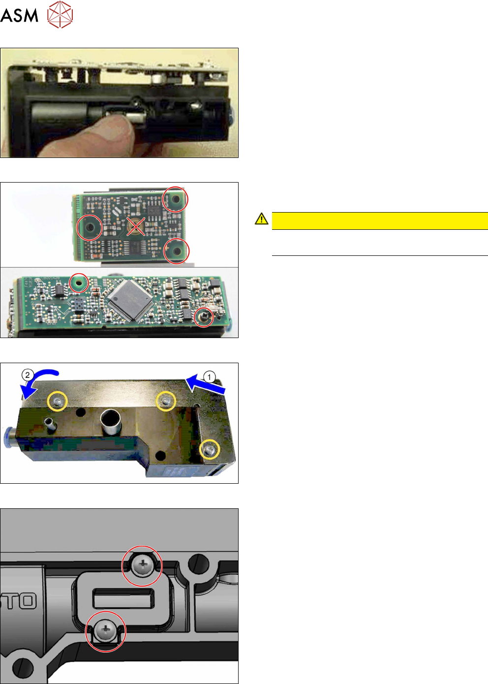
Fig.88: Positioning the top part of the board
► Place the top part of the board onto the housing.
Fig.89: Fastening the board
Fasten the board with five self-tapping screws. To do
so, proceed as follows:
CAUTION!
If possible, always use new screws of type PT-
WN1442-2.5X8-PT10.
.
► First check the thread by turning the screws
slightly to the left.
► Then fasten the screws with a torque of 0.2Nm.
Fig.90: Fitting the cover
► (1) Fit the cover at the top and (2) close it over
the printed circuit board.
► Fasten the cover with three screws. To do so,
proceed as follows:
– First check the thread by turning the screws
slightly to the left.
– Then fasten the screws with a torque of
0.2Nm.
Fig.91: Fitting the cover
► Fix the membrane cover into place on the PRV
with two screws.
► Follow the removal instructions in reverse order for further installation.
Also observe the installation instructions in the following section:
6.1 "Replacing the PRV" [}47]