00197490-03_SM_CP20-P-M2_EN保养维护.pdf - 第71页
8 Return unit and return cylinder 8.1 Replacing the return unit Service Manual SIPLACE SpeedStar (C&P20 P / C&P20 M2) 03/2018 71 8 Return unit and return cylinder 8.1 Replacing the return unit Parts ● Return unit…

7 Holding circuit, aperture ring and silencer
7.4 Vacuum sensor holding circuit board for SIPLACE C&P20P
70 Service Manual SIPLACE SpeedStar (C&P20 P / C&P20 M2) 03/2018
8 Return unit and return cylinder
8.1 Replacing the return unit
Service Manual SIPLACE SpeedStar (C&P20 P / C&P20 M2) 03/2018 71
8 Return unit and return cylinder
8.1 Replacing the return unit
Parts
●
Return unit [03007696-xx]
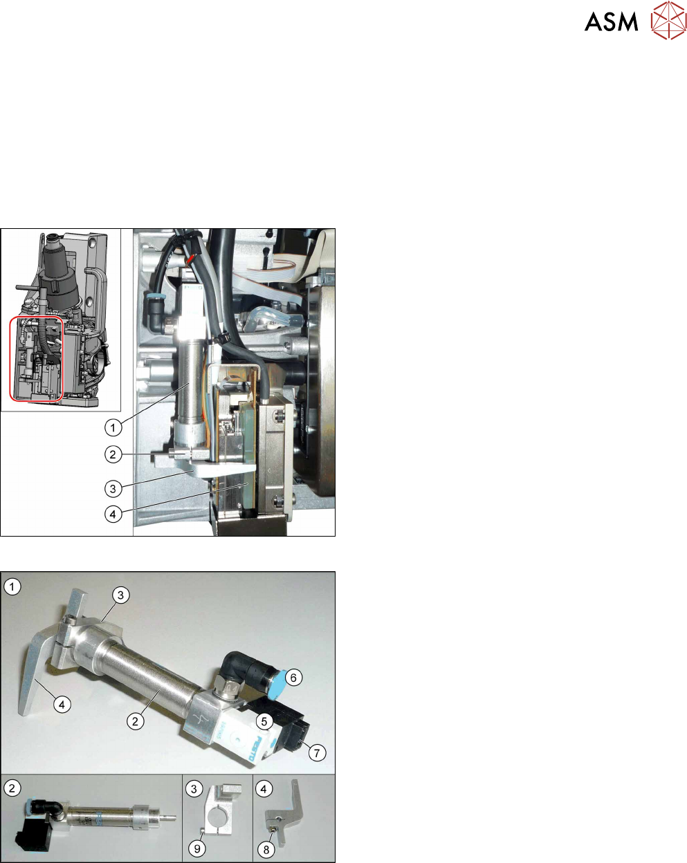
Overview
Fig.109: Overview of return unit on the head
1. Return cylinder
2. Return cylinder holder
3. Driver lever for Z axis
4. Rotor on Z motor
The return unit is installed on the Z axis and is re-
sponsible for protecting the Z axis from damage, by
moving it into a safe area in the case of unexpected
events (e.g. power cuts or machine shutdown).
Fig.110: Overview of return unit
1. Return unit assembly
2. Return cylinder
3. Return cylinder holder
4. Driver lever
5. Solenoid valve
6. Compressed air connection
7. Electrical connection
8. Fastening screw for driver lever (4)
9. Fastening screw for "return cylinder holder"(3)
8 Return unit and return cylinder
8.1 Replacing the return unit
72 Service Manual SIPLACE SpeedStar (C&P20 P / C&P20 M2) 03/2018
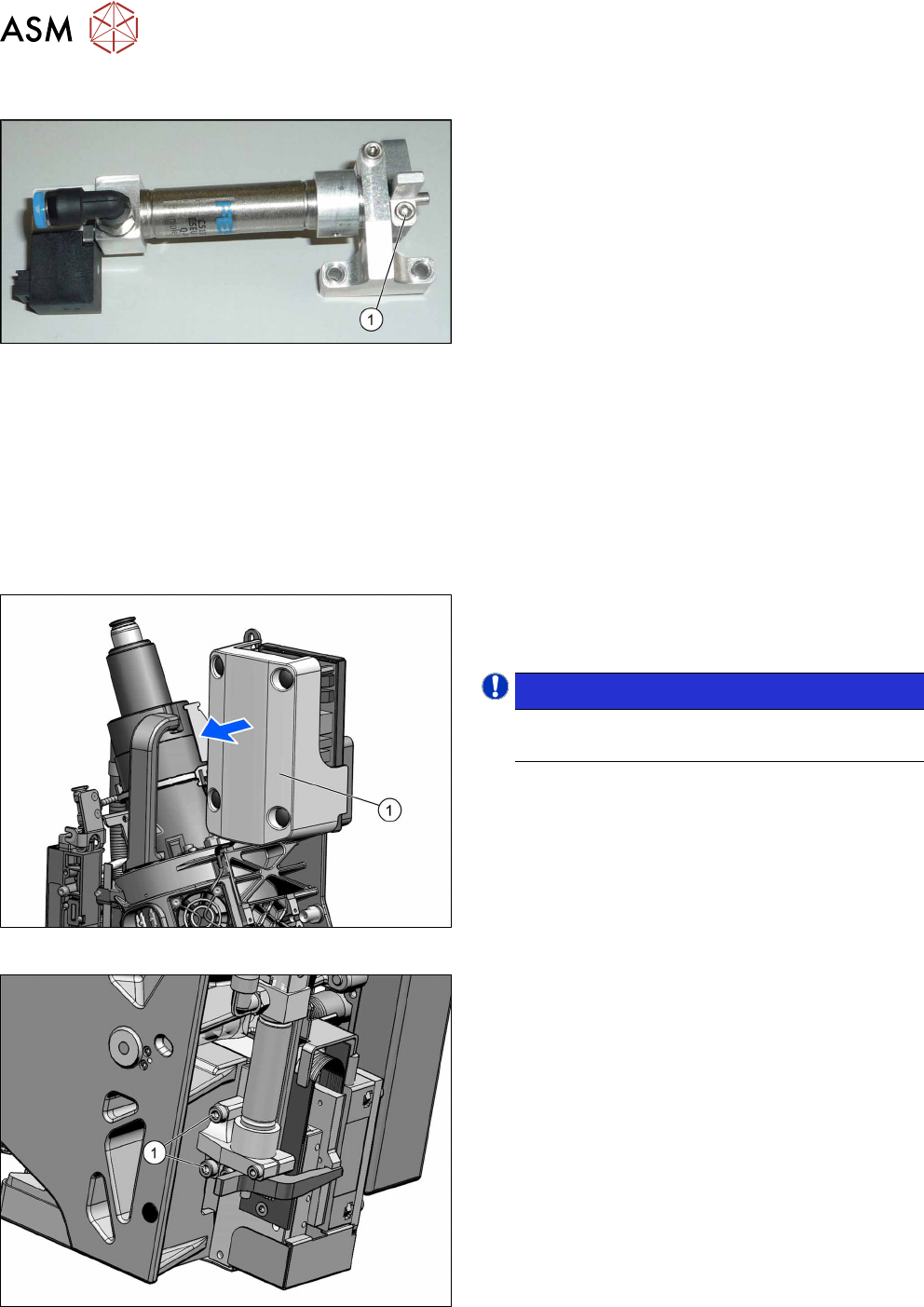
Torque
Fig.111: Screw fastening the driver lever
1. Screw fastening the driver lever
Torque: 1.15 Nm
Preparation
► Remove the head from the machine. For details about removing and fitting the placement
head, refer to the service manual for your machine.
Fit the head on the head mount [03056231‑xx].
► Make sure that the component sensor protective cap is fitted.
1.1.3 "Safety instructions for the component sensor" [}6]
Removal
Fig.112: Pulling the cover off
► Pull the cover(1) off the intermediate distributor.
The cover is fixed by four press studs on the stay
bolts.
NOTICE!
Older heads may not have this cover yet.
.
Fig.113: Dismantling the return unit
► Remove the two screws(1) fastening the return
unit and then carefully pull the return unit slightly
out of the head.
► Unplug all electrical and pneumatic connections.
If necessary, mark their positions to make clear
assignment easier later on.