00197490-03_SM_CP20-P-M2_EN保养维护.pdf - 第85页
11 Software functions 11.2 Calibration Service Manual SIPLACE SpeedStar (C&P20 P / C&P20 M2) 03/2018 85 Fig.127: Automatic Calibration ► Select Heads and cameras. ► Click on the Continue button. Follow the instr…
11 Software functions
11.2 Calibration
84 Service Manual SIPLACE SpeedStar (C&P20 P / C&P20 M2) 03/2018
11.2 Calibration
Overview
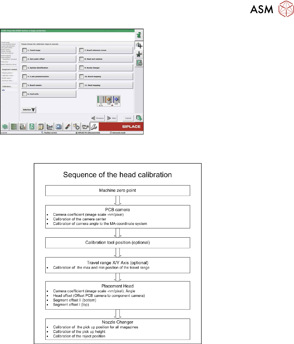
With the calibration of the component camera the following values are determined:
the relationship of "camera pixel size to resolution of machine measuring system (X,Y)", the "cam-
era center point in X and Y direction" and the "torsion angle of the CCD sensor in the camera".
After that, the head offset and the segment offsets for the top and bottom are determined.
●
Head offset: the head offset is the distance between the PCB camera and the nozzle (seg-
ment1). The target is a fixed value (X=0 and Y=‑105mm) to which an offset value (from the
head calibration) is added.
●
Segment offset top: the top segment offset involves turning the calibration tool in the compo-
nent camera in 0°, 90°, 180° and 270°. The value determined is that of the rotating center of
the nozzle tip in relation to the component camera center in the X and Y direction.
●
Segment offset bottom: the bottom segment offset involves recording and measuring the
calibration tool in the 0°, 90°, 180° and 270° positions. The value determined is that of the ro-
tating center point of the nozzle tip when the Z axis is extended in relation to the PCB camera.
Segment1 forms the reference (X=0,Y=0) to the other segments.
11.2.1 Calibrating the heads and cameras (SW70x)
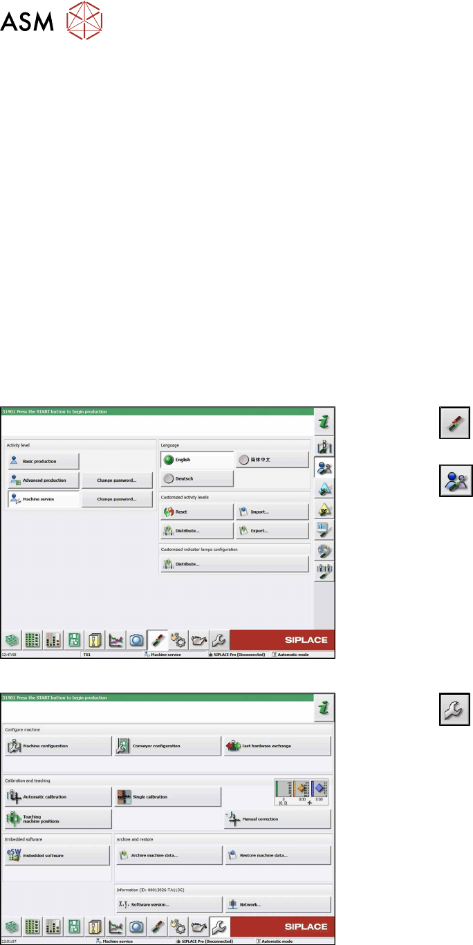
Fig.125: Select operator level
► Click the
button to enter the Settings
menu.
► Click the
button to open the Check and set
user settings menu.
► Switch over to the operator level Machine ser-
vice.
Fig.126: Service Menu
► Click the
button to enter the Service menu.
► Click the Automatic calibration button.
11 Software functions
11.2 Calibration
Service Manual SIPLACE SpeedStar (C&P20 P / C&P20 M2) 03/2018 85
Fig.127: Automatic Calibration
► Select Heads and cameras.
► Click on the Continue button.
Follow the instructions on the next pages:
► On the next page, select the gantries on which
the heads to be calibrated are located and then
click on the Next button.
► The next step is to check the calibration condi-
tions (nozzle, calibration tool etc.). Follow the
instructions provided.
After this step, calibration will begin. All required inter-
mediate steps (head height etc.) will be performed
automatically.
11.2.2 Calibration procedure
Fig.128: C&P calibration procedure
11 Software functions
11.3 Transferring the head specific data (from SW701)
86 Service Manual SIPLACE SpeedStar (C&P20 P / C&P20 M2) 03/2018
11.3 Transferring the head specific data (from SW701)
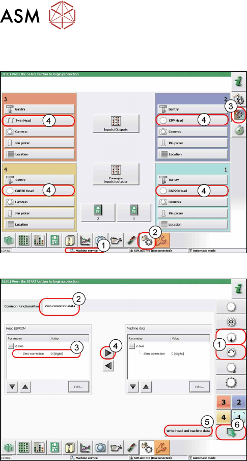
Fig.129: Overview of locations
After changing the head hardware, the new head data
needs to be made available from the head EPROM of
the software.
► Turn the machine on.
► Select the operator level Service (Cus-
tomer)(1).
► Switch over to the menu Check sensors and
functions(2).
► Select the button Check sensors and functions
of specific components(3).
► Select the button(4) for the head on the relevant
gantry.
Fig.130: Zero correction data
► Select the Z axis/star axis (1).
► Select Zero correction data(2).
This is where the axis data (Z and star axes) can be
written from the head EPROM to the machine data.
Depending on the head type, you can also write the Z
and rotary axis data from the machine data to the
head EPROM.
► Select the line Zero correction data(3).
► Move the value out of the head EPROM and into
the machine data (4).
► Select Write head and machine data(5).
► The arrow button (6) takes you back one menu
level.