00197490-03_SM_CP20-P-M2_EN保养维护.pdf - 第22页
3 Usability package 3.2 Fitting the usability kit for SIPLACE C&P20P 22 Service Manual SIPLACE SpeedStar (C&P20 P / C&P20 M2) 03/2018 Fig.18: Fitting the board cover 3 ► Screw a press stud to each of the fo…
3 Usability package
3.2 Fitting the usability kit for SIPLACE C&P20P
Service Manual SIPLACE SpeedStar (C&P20 P / C&P20 M2) 03/2018 21
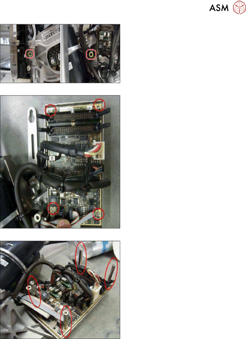
Fig.15: Attach markings 2
► Attach the two O-shaped markings as shown in
the diagram.
First clean the surface with a lint-free cloth,
moistened with ethanol.
Fig.16: Fitting the board cover 1
► Remove the four fillister head screws (hexagon
socket ISO4762M3x6).
Fig.17: Fitting the board cover 2
► Fit the four spacer bolts (type B/la-M3x45–A2).
Secure the spacer bolts with Loctite 222.
3 Usability package
3.2 Fitting the usability kit for SIPLACE C&P20P
22 Service Manual SIPLACE SpeedStar (C&P20 P / C&P20 M2) 03/2018
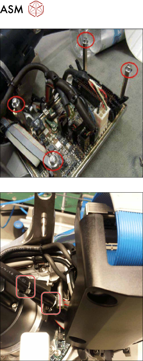
Fig.18: Fitting the board cover 3
► Screw a press stud to each of the four spacer
bolts. Secure the press studs with Loctite 222.
Fig.19: Fitting the board cover 4
To avoid problems with fitting the board cover, check
the cables as follows:
► Pay attention to the position of the cable.
► Make sure that the camera cable on the holding
plate is fastened into place with two cable ties.
3 Usability package
3.2 Fitting the usability kit for SIPLACE C&P20P
Service Manual SIPLACE SpeedStar (C&P20 P / C&P20 M2) 03/2018 23
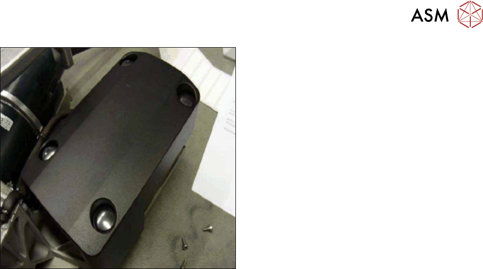
Fig.20: Fitting the board cover 5
► Attach the "Board cover assembly SIPLACE
C&P20P" [03113667‑xx] onto the press studs.
This completes the assembly of the usability kit.