00197490-03_SM_CP20-P-M2_EN保养维护.pdf - 第37页
4 Component camera, Z axis and component sensor 4.5 Replacing the component sensor Service Manual SIPLACE SpeedStar (C&P20 P / C&P20 M2) 03/2018 37 Removal Fig.41: Pulling the cover off ► Pull the cover (1) off…
4 Component camera, Z axis and component sensor
4.5 Replacing the component sensor
36 Service Manual SIPLACE SpeedStar (C&P20 P / C&P20 M2) 03/2018
4.5 Replacing the component sensor
CAUTION
Sensitive lenses
The transmitter and receiver unit lenses on the component sensor are highly sensitive.
► Make sure that you do not damage or contaminate the lens system.
Parts
●
Component sensor for SIPLACE C&P20P [03092400‑xx]
Overview
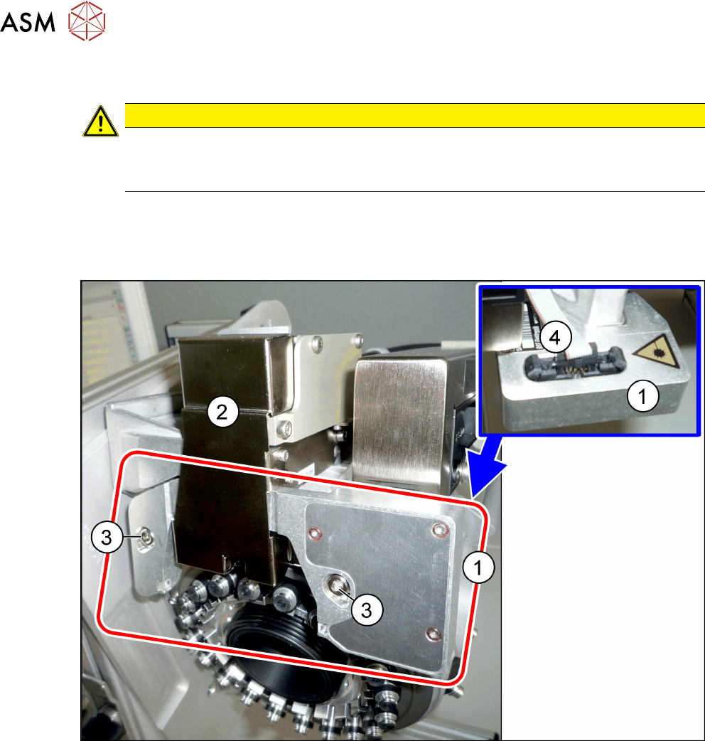
Fig.40: Component sensor and Z axis cover
1 Component sensor on the SIPLACE
C&P20P
2 Z axis cover
3 Two fastening screws for component
sensor
4 Electrical connection on component
sensor
Preparation
► Remove the head from the machine. For details about removing and fitting the placement
head, refer to the service manual for your machine.
Fit the head on the head mount [03056231‑xx].
4 Component camera, Z axis and component sensor
4.5 Replacing the component sensor
Service Manual SIPLACE SpeedStar (C&P20 P / C&P20 M2) 03/2018 37
Removal
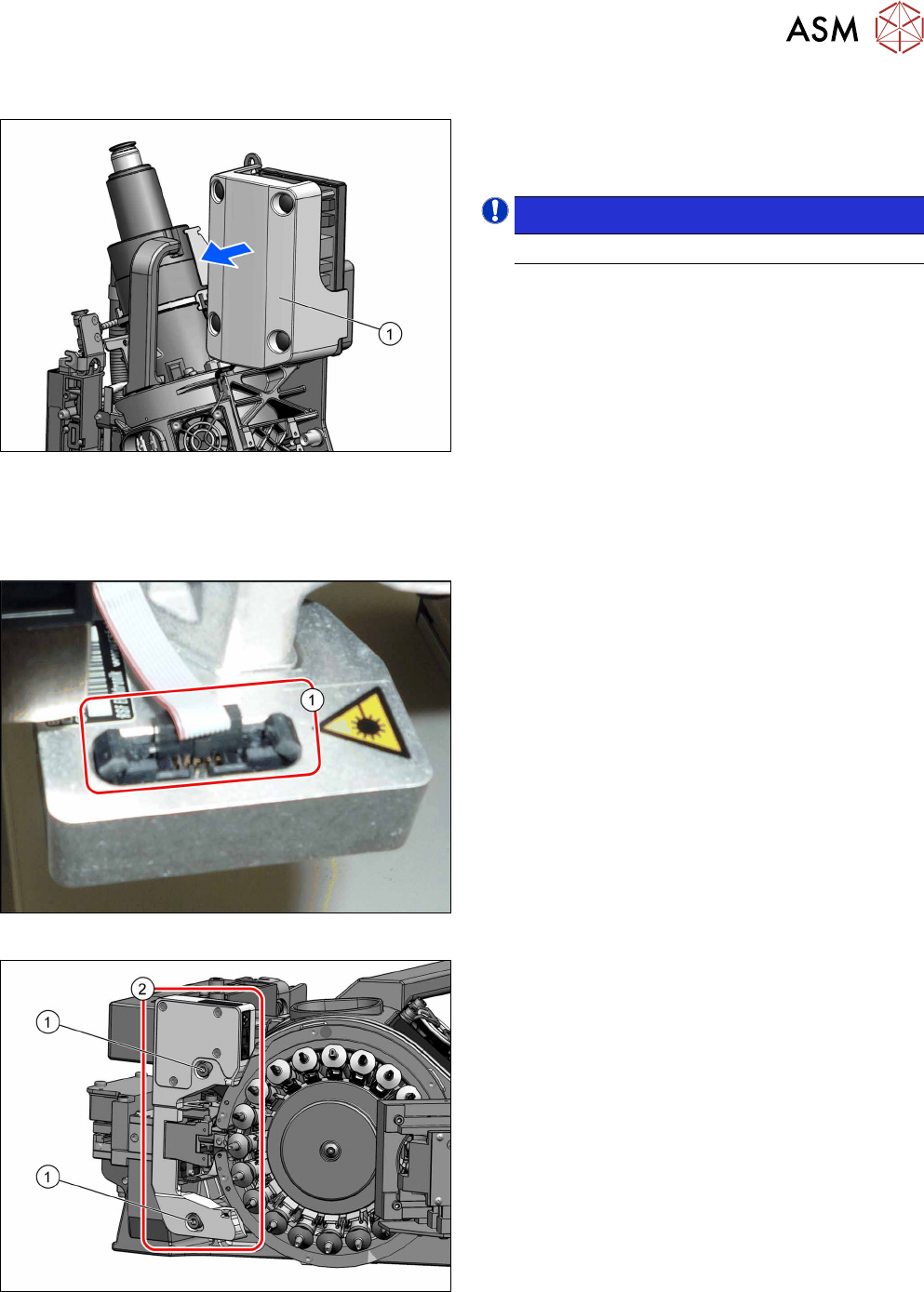
Fig.41: Pulling the cover off
► Pull the cover(1) off the intermediate distributor.
The cover is fixed by four press studs on the stay
bolts.
NOTICE!
Older heads may not have this cover yet.
.
► Dismantle the Z axis cover.
4.2 "Replacing the Z axis cover" [}29]
You can now access the component sensor.
Fig.42: Electrical connection
► Unplug the electrical connection(1) from the
component sensor.
Remove any cable ties. You may want to mark
their positions for easier exact replacement later
on.
Fig.43: Fastening screws
► Remove the two screws(1) fastening the compo-
nent sensor(2) and then remove the component
sensor.

4 Component camera, Z axis and component sensor
4.5 Replacing the component sensor
38 Service Manual SIPLACE SpeedStar (C&P20 P / C&P20 M2) 03/2018
Installation
► Fix the new component sensor with the two fastening screws.
► Plug in the electrical connection. Fasten the cable with cable ties, if required.
► Follow the removal instructions in reverse order for further installation.
Also observe the installation instructions in the following section:
4.2 "Replacing the Z axis cover" [}29]
► Observe in particular the torques specified!
► Calibrate the component sensor.
11.2.1 "Calibrating the heads and cameras (SW70x)" [}84]