00197490-03_SM_CP20-P-M2_EN保养维护.pdf - 第69页
7 Holding circuit, aperture ring and silencer 7.4 Vacuum sensor holding circuit board for SIPLACE C&P20P Service Manual SIPLACE SpeedStar (C&P20 P / C&P20 M2) 03/2018 69 Installation ► Follow the removal ins…
7 Holding circuit, aperture ring and silencer
7.2 Replacing the seal disk on the aperture ring/holding circuit
68 Service Manual SIPLACE SpeedStar (C&P20 P / C&P20 M2) 03/2018
7.2 Replacing the seal disk on the aperture ring/holding
circuit
Parts
●
Sealing disc:
Vacuum mode (aperture ring): sealing disc for SIPLACE C&P20P [03105638-xx]
Compressed air mode (holding circuit): sealing disc for SIPLACE C&P20 [03005120-xx]
●
O-ring:
Vacuum mode (aperture ring): O-ring 40x1.5 [03006234-xx]
Compressed air mode (holding circuit): O-ring 50x1.5 [03046689-xx]
Removal / installation
► Removal and installation follows the same procedure for the holding circuit/aperture ring. For
more information, read section 7.1 "Replacing the holding circuit/reflecting ring" [}61].
7.3 Replacing the silencer (venturi mode only)
Parts
●
Silencer [03043707-xx]
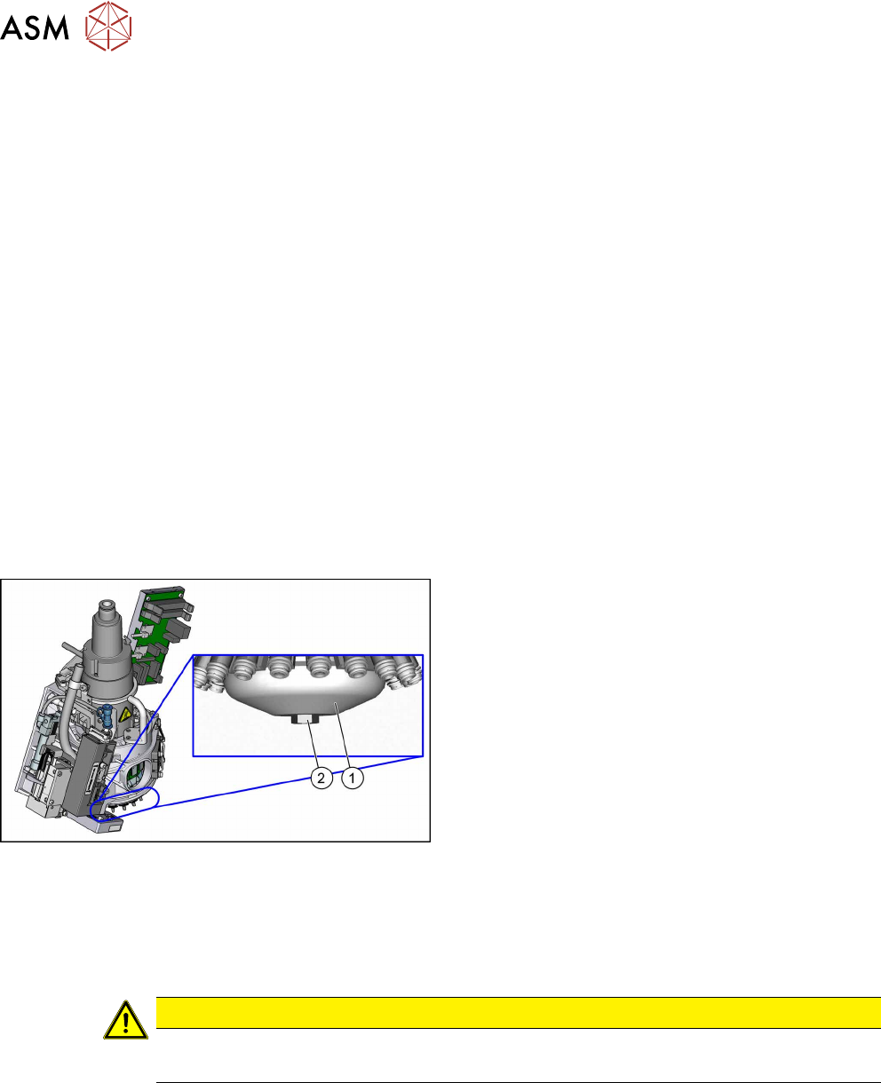
Overview
Fig.107: Silencer
1. Silencer for holding circuit
2. Fastening screw
Preparation
► Remove the head from the machine. For details about removing and fitting the placement
head, refer to the service manual for your machine.
Fit the head on the head mount [03056231‑xx].
CAUTION
Camera
► Make sure that you do not damage or contaminate the camera lens system.
► Make sure that the component sensor protective cap is fitted.
1.1.3 "Safety instructions for the component sensor" [}6]
Removal
► Remove the screw fastening the silencer.
► Carefully lever out the silencer.
7 Holding circuit, aperture ring and silencer
7.4 Vacuum sensor holding circuit board for SIPLACE C&P20P
Service Manual SIPLACE SpeedStar (C&P20 P / C&P20 M2) 03/2018 69
Installation
► Follow the removal instructions in reverse order for further installation. Also observe the fol-
lowing instructions:
CAUTION
Installation instructions
► Carefully press the new silencer down, onto the holding circuit.
► Carefully hand-tighten the screw fastening the silencer.
7.4 Vacuum sensor holding circuit board for SIPLACE
C&P20P
The "Vacuum sensor holding circuit SIPLACE C&P20P" board [03095143‑xx] is fitted on SIPLACE
C&P20P and C&P20M2 heads.
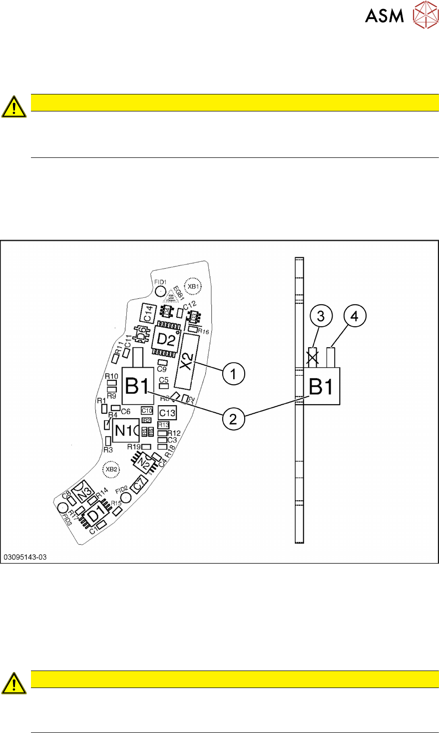
Fig.108: Vacuum sensor holding circuit board for SIPLACE C&P20P [03095143‑xx]
1 Plug X2 (to intermediate distributor) 2 Pressure sensor (holding circuit/aper-
ture ring)
3 Bottom hose connection on pressure
sensor
→ Do not use!
4 Top hose connection on pressure
sensor
CAUTION
Only use the top hose connection
The bottom hose connection(3) directly above the board must remain free.
► Only use the top hose connection(4).

7 Holding circuit, aperture ring and silencer
7.4 Vacuum sensor holding circuit board for SIPLACE C&P20P
70 Service Manual SIPLACE SpeedStar (C&P20 P / C&P20 M2) 03/2018