00197490-03_SM_CP20-P-M2_EN保养维护.pdf - 第6页
1 Introduction 1.2 Other instructions 6 Service Manual SIPLACE SpeedStar (C&P20 P / C&P20 M2) 03/2018 1.1.3 Safety instructions for the component sensor Fig.1: Component sensor protective cap [03112729‑xx] WAR…
1 Introduction
1.1 Safety instructions
Service Manual SIPLACE SpeedStar (C&P20 P / C&P20 M2) 03/2018 5
1 Introduction
This document is a manual or reference work for performing service work on the SIPLACE®
C&P20 P and C&P20 M2 placement head types.
1.1 Safety instructions
DANGER
Nonobservance of these safety instructions may cause injury to personnel and dam-
age to the machine!
► Please observe the safety instructions in the user manual of the relevant machine
for all work!
1.1.1 Conventions for the use of safety instructions and symbols
Safety Information
This manual contains notes that must be observed to guarantee your personal safety and to avoid
damage to equipment. These notes are highlighted by warning triangles and are indicated as fol-
lows according to the level of risk:
DANGER
Definition
For the purposes of this manual, this indicates that fatal or severe injuries or considerable
damage to property will occur if this hazard warning is not observed.
WARNING
Definition
For the purposes of this manual, this indicates that fatal or severe injuries or considerable
damage to equipment may occur if these warning instructions are not followed.
CAUTION
Definition
For the purposes of this manual, this indicates that minor injuries or damage to property
may occur if this caution is not observed.
NOTICE
Definition
For the purposes of this manual, this note provides information about the product or indic-
ates a part of the manual that requires particular attention.
Symbols
Example Description
Next This typeface marks controls and interface elements in the software.
► These symbol indicates actions that have to be performed by the operator.
1.1.2 Safety instructions on hazardous materials
CAUTION
Observe the safety data sheets
Observe the applicable safety data sheet, when handling hazardous materials (e. g. Loctite
241, ethanol).
1 Introduction
1.2 Other instructions
6 Service Manual SIPLACE SpeedStar (C&P20 P / C&P20 M2) 03/2018
1.1.3 Safety instructions for the component sensor
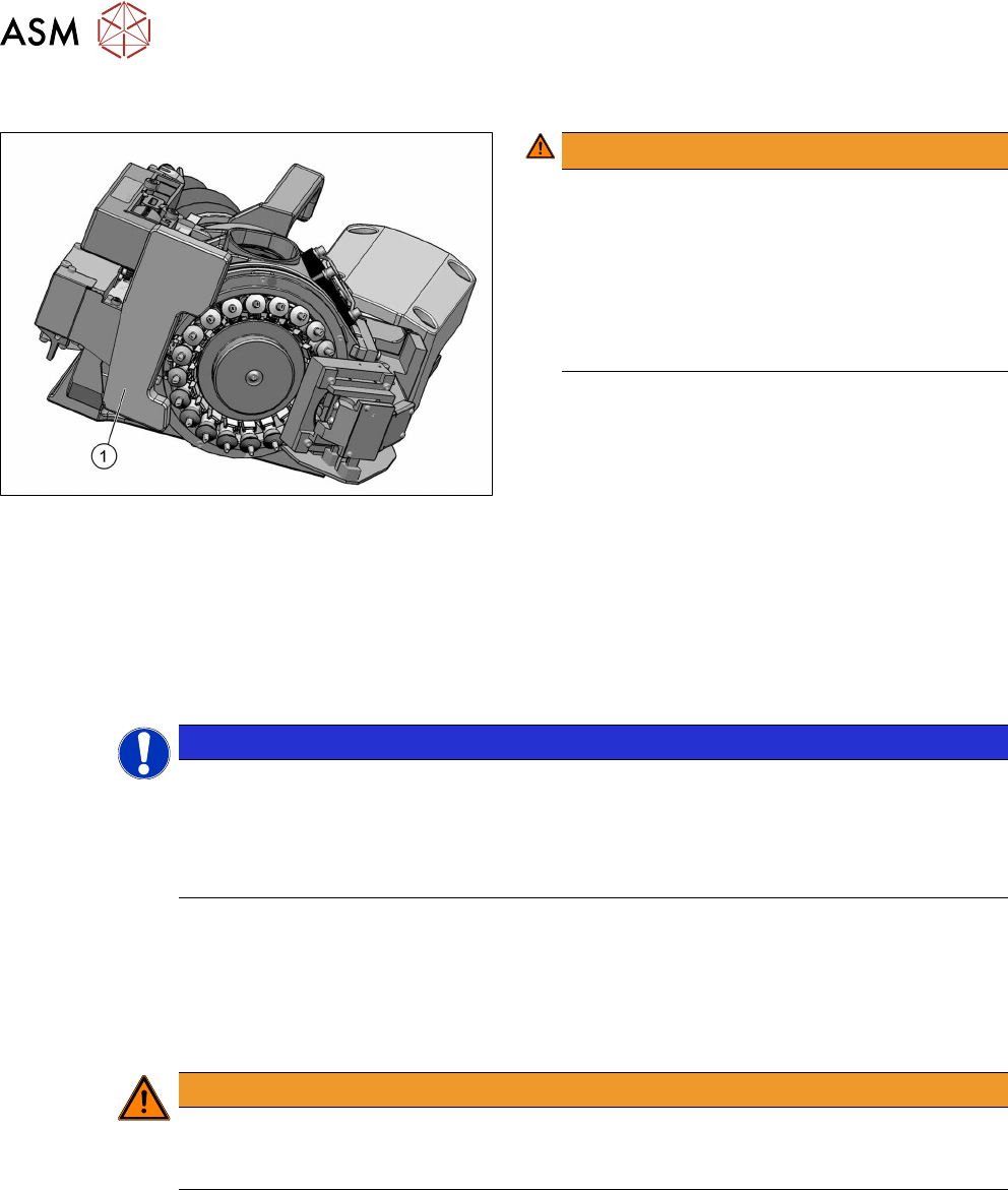
Fig.1: Component sensor protective cap [03112729‑xx]
WARNING!
Prisms on the component sensor
The component sensor prisms, underneath the
placement head, are easily damaged.
Never place the placement head down on the
component sensor.
For all work, fit the protective cap [03112729‑xx]
onto the component sensor of the placement
head.
.
1.2 Other instructions
1.2.1 Environmentally-friendly disposal of materials and components
Our products are manufactured using only materials and parts that can be easily separated and
disposed of in an environmentally-friendly way.
NOTICE
Observe the applicable regulations
The company operating the system has sole responsibility for the proper, environmentally-
friendly disposal of machines, working materials, consumable materials and wear parts.
► Please observe your national statutory provisions for waste disposal and environ-
mental protection.
1.2.2 Use of original accessories and spare parts
Only use original spare parts and authorized accessories. The use of other parts will affect safety
and will invalidate the liability for any consequential damage.
1.2.3 Information about this service manual
WARNING
Additional qualifications required
The service work described in this manual may only be performed by specially trained ser-
vice technicians, with appropriate qualifications and expertise.
If you should have any questions during the service work, please contact the SIPLACE customer
hotline directly or send an e-mail to hotline.siplace@asmpt.com.

1 Introduction
1.2 Other instructions
Service Manual SIPLACE SpeedStar (C&P20 P / C&P20 M2) 03/2018 7
1.2.4 ESD guidelines
1.2.4.1 What does ESD mean?
Almost all of the modules in use today are equipped with highly integrated Metal-Oxide-Semicon-
ductor (MOS) blocks and components. The manufacturing techniques used mean that these elec-
tronic components are extremely sensitive to overvoltage and thus to electrostatic discharge.
The abbreviation for such modules is 'ESD' (Electrostatic Sensitive Device).
’ESD’ is used internationally. The following symbol on cabinet rating plates,
racks or packaging indicates that components which are sensitive to electro-
static discharge have been used and thus that the modules concerned are also
touch-sensitive.
ESDs can be destroyed by voltages and power levels that are far below the level that can be per-
ceived by humans. Such voltages occur if a person touches a component or module without
earthing themselves. Components that are exposed to such overvoltage do not generally appear
to be defective immediately - incorrect behavior starts after the component or module has been in
operation for some time.
1.2.4.2 Important measures to protect against static charging
► Most plastics can easily become charged and must therefore be kept away from at-risk com-
ponents.
► Always ensure that people, the workplace and packaging are safely earthed when handling
electrostatic sensitive components.
1.2.4.3 Handling ESD modules
Do not touch electronic modules unless it is absolutely essential to do so in order to carry out other
work. If it is necessary, make sure that you do not touch the pins or printed conductors when you
pick up flat modules.
Do not touch components unless:
●
You are constantly earthed by an ESD wrist strap or
●
You are wearing ESD shoes or ESD shoe earthing strips on an ESD floor.
Always discharge yourself before you touch an electronic module. To do this, simply touch a con-
ductive and earthed object immediately before you touch the module (such as unpainted parts of a
switch cabinet, a water pipe, etc.).
Do not allow modules with chargeable and highly insulating materials to touch one another, e.g.
plastic films, insulating table surfaces or items of clothing made from synthetic fibers.
Always place the modules on a conductive surface (table with an ESD coating, conductive ESD
foam, ESD bag or container).
Do not move the assemblies near to data view devices, monitors or television units. Keep a min-
imum distance of 10 cm to monitors.
1.2.4.4 Measurements and modifications to ESD modules
Do not take measurements on the modules unless the following conditions are fulfilled:
●
The measuring device is earthed (e.g. via PE conductors) or
●
You discharge the measuring head just before taking measurements with a potential-free
measuring device (e.g. by touching an unpainted metal part of the controller casing).
► Always use an earthed soldering iron if you carry out any soldering work.