00197490-03_SM_CP20-P-M2_EN保养维护.pdf - 第47页
6 Pressure control valve (PRV) 6.1 Replacing the PRV Service Manual SIPLACE SpeedStar (C&P20 P / C&P20 M2) 03/2018 47 6 Pressure control valve (PRV) 6.1 Replacing the PRV Parts ● Pressure control valve (PRV) [031…

5 DP drives
5.3 Replacing the clamping plate at the DP drive
46 Service Manual SIPLACE SpeedStar (C&P20 P / C&P20 M2) 03/2018
6 Pressure control valve (PRV)
6.1 Replacing the PRV
Service Manual SIPLACE SpeedStar (C&P20 P / C&P20 M2) 03/2018 47
6 Pressure control valve (PRV)
6.1 Replacing the PRV
Parts
●
Pressure control valve (PRV) [03106620‑xx]
Overview
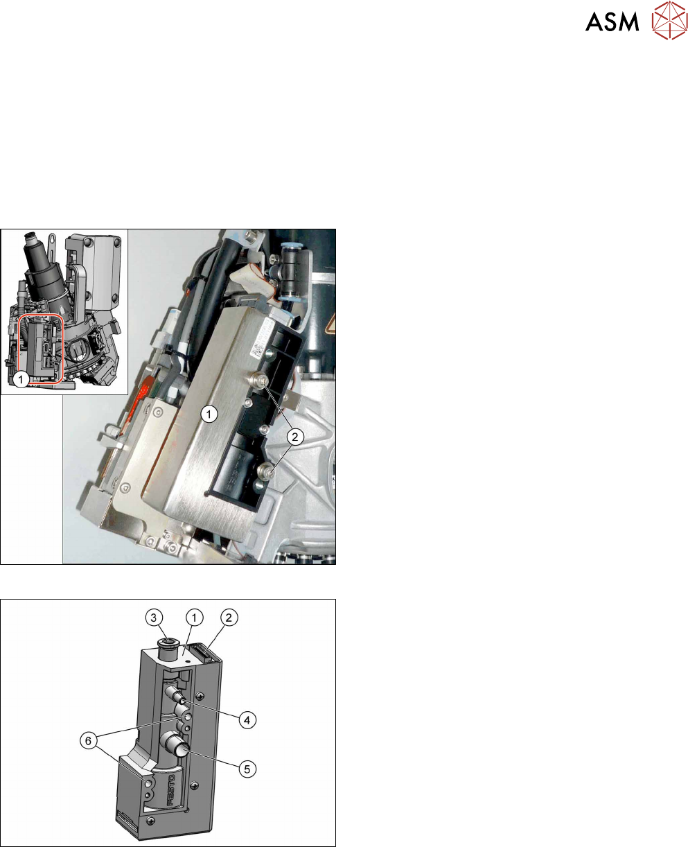
Fig.58: Pressure control valve fastening screws
1. Pressure control valve (PRV)
2. Two fastening screws
Torque: 0.9Nm
Fig.59: Overview of PRV
1. Strain relief with intermediate plate
2. Energy and data supply
3. Compressed air connection
4. Vacuum/air blast for pickup/placement circuit
5. Exhaust air, for cooling the X linear motor
6. Fastening screws on PRV
The pressure control valve supplies the pickup/place-
ment circuit with vacuum during the pickup process
and switches over to air blast during placement.
Preparation
► Remove the head from the machine. For details about removing and fitting the placement
head, refer to the service manual for your machine.
Fit the head on the head mount [03056231‑xx].
► Make sure that the component sensor protective cap is fitted.
1.1.3 "Safety instructions for the component sensor" [}6]
6 Pressure control valve (PRV)
6.1 Replacing the PRV
48 Service Manual SIPLACE SpeedStar (C&P20 P / C&P20 M2) 03/2018
Removal
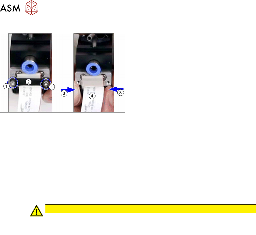
Fig.60: Disconnecting the energy and data supply cable
► Remove the two screws fastening the strain re-
lief(1) and then remove the strain relief (2).
► Press the two locks(3) together and unplug the
energy and data supply cable(4).
► Open the cable clamp fastening the cable to the component camera.
► Disconnect the hoses to the compressed air and from the vacuum/blast air and exhaust air. If
necessary, mark their positions to make clear assignment easier later on.
► Remove the two screws fastening the PRV and then remove the PRV.
Installation
► Fit the new PRV. Tighten the screws fastening the PRV with a torque of 0.9Nm.
► Reconnect to the electrical and compressed air systems.
Pay attention to the locking of the connectors.
► Follow the removal instructions in reverse order for further installation. Also observe the fol-
lowing instructions:
CAUTION
Installation instructions
► Perform "zero correction" for the pressure control valve. (See section 6.4 "Calibrating
the digital PRV" [}60]).