00193897-0302_AI_MTC2+BE_DE+EN.pdf - 第102页
Assembly instructions MTC2 and Component docking unit on SIPLACE HF and X-se ries Edition 07/2009 100 2 T ab. 2.7 - 1 Component docking unit: Connectors SIPLACE HF (from A001) and X-series. 2 : Route the cables and hose …
Assembly instructions MTC2 and Component docking unit on SIPLACE HF and X-series
Edition 07/2009
99
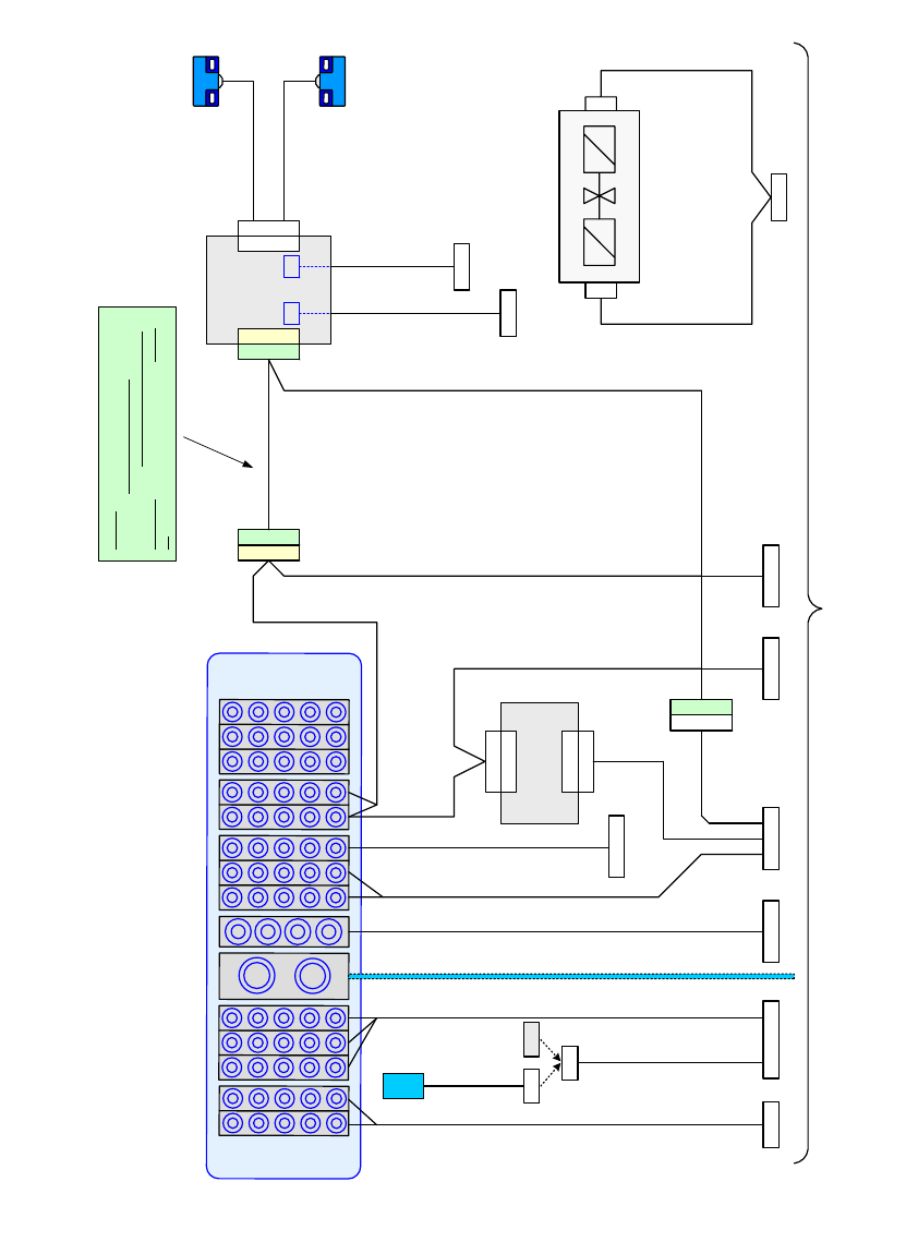
2.7.1 Circuit diagram
Einzug Ventil Ein/Aus
03021030-W1
03021030-W2
Einzug Ventil Ein/Aus
X6
W1
W2
Abwurfbehälter
03022078-xx
1-Wire Hub PPW
03020668-xx
X7
X2*3
X1*2
X2*h
X2
X4*h
X4
X2*4
(CAN-Out) (CAN-In)
(Haltekreis)
Steuereinheit für
Schneidgerät
03006411-xx
X1*f
Splice Detect
03021021-W1
Sicherheit
Sicherheit
03021020-W1
03021020-W2
Brückenstecker
(BE-Klappe)
03021042-xx
Bulk-Case
Leistung
03021022-W1
Signalisierung
Signalisierung
Signalisierung
03021019-W1
03021019-W2
03021019-W3
CAN-Bus / 1-Wire
03021018-xx
O
D
U
-
MA
C
B
u
ch
sen
t
eil cp
l.
X1*q
X2*q
X1
X2
PPW 1
PPW 2
03008677-
xx
1-Wire PPW
03021247-W2
1-Wire PPW
03021247-W1
X1*fX1*f
(Option)
(Option)
Schalter BE-Klappe
03026242-xx
Kabelbaum HF / BE-Wagen Einzug R2 03021017-xx (Stellplatz 1-4)
mit 1-Wire Hub PPW
30.11.2006
X1*6 X1*5
X3*q
X3*q
X1*q_2
X1*q
X**1
Signalisierung
03021019-W4
Versorgung 1-Wire Hub
03037882-W1
Versorgung 1-Wire Hub
03037882-W2
X1*3X1
Hinweis:
Das Kabel: Versorgung 1-Wire Hub
03037882-xx
gehört nicht zum Kabelbaum HF / BE-Wagen
Einzug R2 03021017-xx, sondern zum Einzug
R2 03021878-xx.
Power
Power
24V
S1
BE
PP
Sensor S1
Sensor S2
Schnittstelle zur Grundmaschine
X1_AUS_14 X1_EIN_12
14
Magnet-Impuls-Ventil
03002003-xx
12
X1*a
X1*b
Adr.
FCU
CAN-Bus / 1-Wire
03021018-xx
Druckluftleitung
2
Fig. 2.7.3 Diagram cable harness: Docking unit with 1-wire hub (HF, Series No. from A001) / X-series

Assembly instructions MTC2 and Component docking unit on SIPLACE HF and X-series
Edition 07/2009
100
2
Tab. 2.7 - 1 Component docking unit: Connectors SIPLACE HF (from A001) and X-series.
2
: Route the cables and hoses in the cable duct.
2
2
2
2
2
2
2
2
2
SIPLACE HF (from A001) and X-series
Cable harness component docking unit
S-tape feeders (03021067-)
Location 1 Location 2 Location 3 Location 4
X110
ODU connector on docking unit frame
Splice Detection (Option)
X1
030021021-
Power
X1*1
03021022-
X111
03002491-
X121
03002492-
X131
03002493-
X141
03002494-
Component signalling
24V 1-wire
X1*2
03021019-
X112
03002541-
X122
03002530-
X132
03002534-
X142
03002546-
Component safety
X1*3
03021020-
X113
03002542-
X123
03002531-
X133
03002535-
X143
03002547-
CAN bus / 1 wire (in)
X1*5
03021018-
X115
03010051-
X125
03010053-
X135
03010054-
X145
03010052-
CAN bus / 1 wire (out)
X1*6
03021018-
X116
03010050-
X126
03010054-
X136
03010059-
X146
03010051-
Docking unit valve on/off
X2*4
03021030-
X2fn
03017446-
X2gn
03017447-
X2hn
03017448-
X2kn
03017449-
Pneumatic supply bulk case 03004200- 03004679- 03004679- 03004679- 03004679-
Option nozzle changer /
Reject bin sensors
1-wire hub / CAN bus X1*q
Supply 1-wire hub X3*q
Assembly instructions MTC2 and Component docking unit on SIPLACE HF and X-series
Edition 07/2009
101
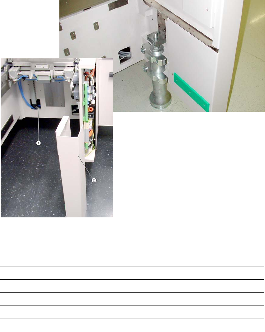
: Stow connectors, couplings and further cable material in the opening in the machine frame. (1).
: Fit the side covers (2) of
the machine frame.
2
Fig. 2.7.4 Component docking unit with outer cover (HF-series, location 2-4).
: If provided, mount the conveyor cover, nozzle changer and reject bin sensors. For further in-
formation, see the latest
instructions:
00193892-xx Assembly instructions conveyor cover SIPLACE HF-series / X-series / D3
00193756-xx Assembly instructions nozzle changer SIPLACE HF-series
00194550-xx Assembly instructions reject bin sensors SIPLACE HF-series
00194482-xx Assembly instructions nozzle changer SIPLACE X-series
00
194716-xx Assembly instructions reject bin sensors SIPLACE
X-series
2
2