00193897-0302_AI_MTC2+BE_DE+EN.pdf - 第94页
Assembly instructions MTC2 and Component docking unit on SIPLACE HF and X-se ries Edition 07/2009 92 2.6.3 Final work af ter installa tion of the component docking unit: : Route the cables and hose s in the cable duct. :…
Assembly instructions MTC2 and Component docking unit on SIPLACE HF and X-series
Edition 07/2009
91
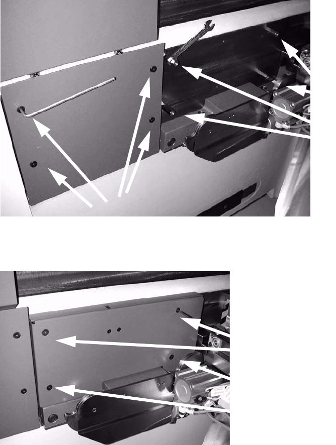
: Fix the bolts (inside) for assembly of the machine cover.
: Mount the side wall on the left next to it.
: Screw the inner and outer machine cover in place with the four nuts and bolts.
2
2
2
2
2
2
Assembly instructions MTC2 and Component docking unit on SIPLACE HF and X-series
Edition 07/2009
92
2.6.3 Final work after installation of the component docking unit:
: Route the cables and hoses in the cable duct.
: Stow connectors, couplings and further cable materia
l in the opening in the machine frame.
: If provided, mount the conveyor cover, nozzle chan
ger and reject bin sensors. For further in-
formation, see the latest inst
ructions:
00193892-xx Assembly instructions conveyor cover SIPLACE HF-series / X-series / D3
00193756-xx Assembly instructions nozzle changer SIPLACE HF-series
00194550-xx Assembly instructions reject bin sensors SIPLACE HF-series
2
: Mount the waste chute.
: Fit the cover over the pneumatic unit or power supply.
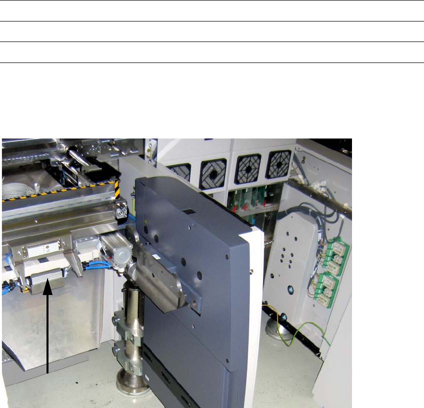
X110 ODU connector
on docking unit frame
2
Fig. 2.6.6 HF until A001_loc.2/4 with docking unit outside left
Assembly instructions MTC2 and Component docking unit on SIPLACE HF and X-series
Edition 07/2009
93
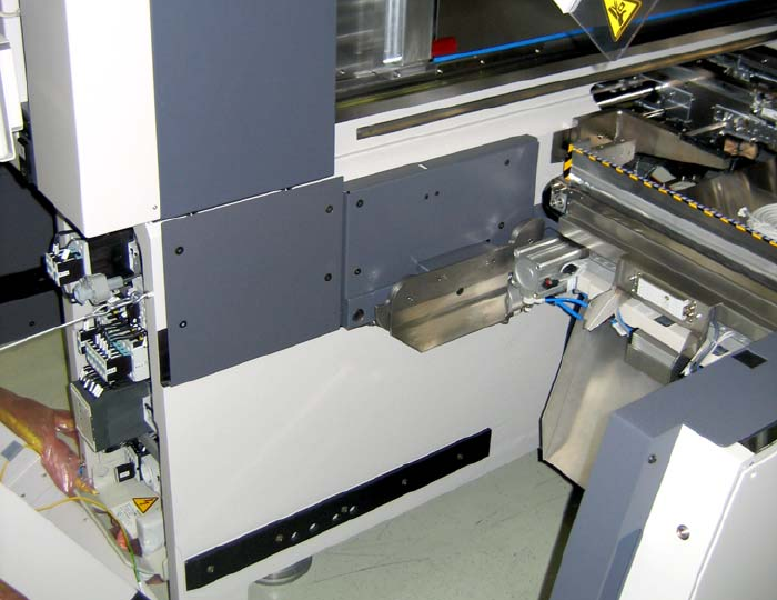
2
Fig. 2.6.7 HF until A001_loc.2/4 with docking unit inside right