00193897-0302_AI_MTC2+BE_DE+EN.pdf - 第87页
Assembly instructions MTC2 and Component docking unit on SIPLACE HF and X-series Edition 07/2009 85 2 Fig. 2.6.4 Assembly of component docking unit 2 2 2 2 2 2 2 2 2 2 2 2
Assembly instructions MTC2 and Component docking unit on SIPLACE HF and X-series
Edition 07/2009
84
2
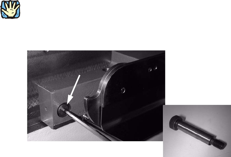
Observe sequence:
The reamed bolt must be tightened first and then the
other fixing bolts. This ensures correct sea-
ting of the MTC slide-in framework. 2
: Screw in the reamed bolt and then the fixing bolts without tightening.
: First tighten the reamed bolt, then the fixing
bolts on the inside of the machine.
2
Fig. 2.6.3 Reamed bolt
Assembly instructions MTC2 and Component docking unit on SIPLACE HF and X-series
Edition 07/2009
85
2
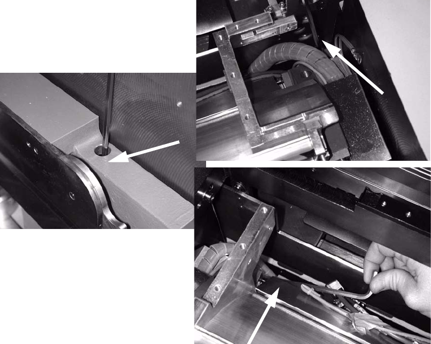
Fig. 2.6.4 Assembly of component docking unit
2
2
2
2
2
2
2
2
2
2
2
2
Assembly instructions MTC2 and Component docking unit on SIPLACE HF and X-series
Edition 07/2009
86
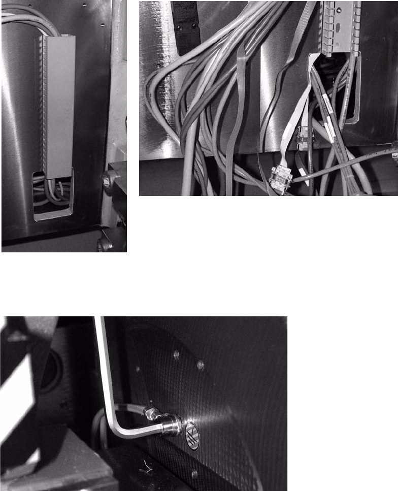
: Re-establish all electrical connections.
: Pull the cables that run in the cable duct below the empty tape cutter out of the machine frame.
2
: Connect the cables and compressed-air line as shown in the circuit diagram.
: Connect the earthing cable.
2
2