00193897-0302_AI_MTC2+BE_DE+EN.pdf - 第113页
Assembly instructions MTC2 and Component docking unit on SIPLACE HF and X-series Edition 07/2009 111 If provided, mount the nozzle changer an d reject bin sensors. For furthe r information, see the latest instructions: 2…
Assembly instructions MTC2 and Component docking unit on SIPLACE HF and X-series
Edition 07/2009
110
2
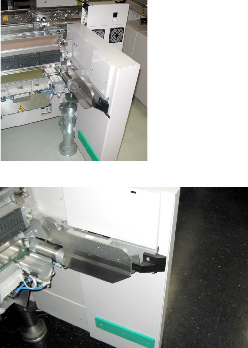
Fig. 2.8.4 Component docking unit in 1-gantry placement area
2
Fig. 2.8.5 Component docking unit in the 2-gantry placement area
2
Assembly instructions MTC2 and Component docking unit on SIPLACE HF and X-series
Edition 07/2009
111
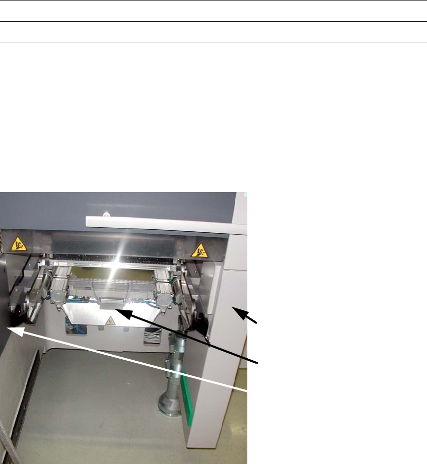
If provided, mount the nozzle changer and reject bin sensors. For further information, see the
latest instructions: 2
00194482-xx Assembly instructions nozzle changer SIPLACE X-series
00194716-xx Assembly instructions reject bin sensors SIPLACE X-series
2
2
Mount parts from retrofit kit
The following parts must be mounted or fitted. 2
1. Cover long EGS centre
2. Machine cover X-F cover cpl. /
Machine cover X-S cover cpl.
3. Wasteþchute
Machine cover plate
X-F or X-S
Wasteþchute
Cover long EGS centre
2
Fig. 2.8.6 Installed retrofit kit
2
: Fit the cover over the pneumatic unit or power supply.

Assembly instructions MTC2 and Component docking unit on SIPLACE HF and X-series
Edition 07/2009
112
2.9 Final work
after installation of the component docking unit
: Reconnect the power supply.
: Configure the "new" machine in the station editor of SIPLACE Pro
as well as under SITEST on
the station computer.
2
: Switch on the machine at the main switch.
: Dock the component trolley to the machine.
: Close the covers.
: Carry out referencing.
: Change to SITEST.
: Measure the marks on the component table.
2.9.1 Dock the component trolley
: Adjust the component trolley to the machine height.
2
Relevant information is provided in the latest operating instructions:
00193921-xx Operating instructions SIPLACE HF
00195284-xx Operating instructions X-series
2