00193897-0302_AI_MTC2+BE_DE+EN.pdf - 第129页
1a 2a 2a 1b 2b 2b 2b Assembly instructions MTC2 and Component docking unit on SIPLACE HF and X-series Edition 07/2009 127 2 Fig. 2.1 1.5 2-gantry placement area : Fixing positions inside (FS 03) 2 Fig. 2.1 1.6 2- gantry …
Assembly instructions MTC2 and Component docking unit on SIPLACE HF and X-series
Edition 07/2009
126
Photos of installation in location 2/4 in 2-gantry placement area 2
: Position the slide-in framework in the machine fram
e about 11 cm away from the front edge.
1a
1b
2
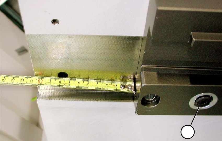
Fig. 2.11.4 2-gantry placement area: Distance to front edge about 11 cm
2-gantry placement area: 2
(1b) Reamed bolt (note position) 2
(2b) Bolts 2
1a 2a2a
1b 2b
2b
2b
Assembly instructions MTC2 and Component docking unit on SIPLACE HF and X-series
Edition 07/2009
127
2
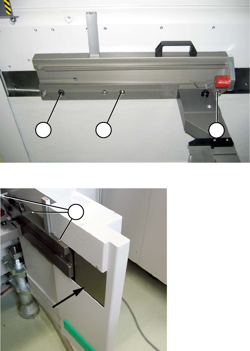
Fig. 2.11.5 2-gantry placement area: Fixing positions inside (FS 03)
2
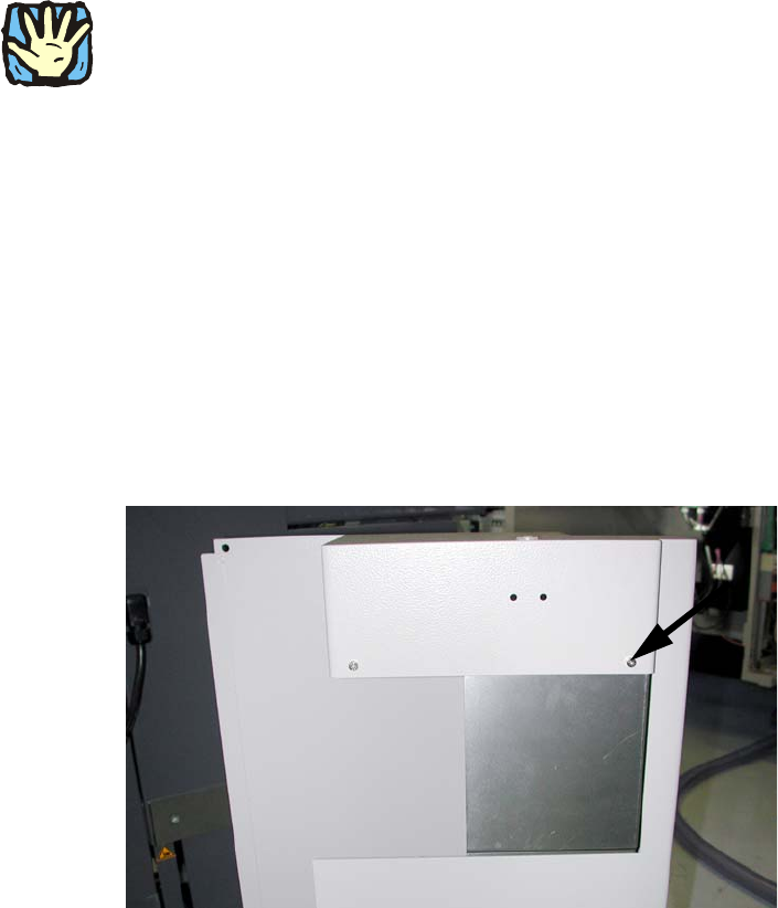
Fig. 2.11.6 2-gantry placement area: Fixing outside with protective cover fitted
Assembly instructions MTC2 and Component docking unit on SIPLACE HF and X-series
Edition 07/2009
128
2.11.1 General installation
2
Observe sequence:
The reamed bolt must be tightened first and then the o
ther fixing bolts. This ensures correct seat-
ing of the MTC slide-in framework. 2
: Screw in the reamed bolt (1a or 1b)
and then the fixing bolts (2a or 2b) without tightening (see
Fig. 2.11.2 and Fig. 2.11.5).
: First tighten the reamed bolt, then the fixing b
olts on the inside of the machine (left).
: Screw the 3 fixing bolts (2a or 2b) on
the machine outer side (right side) of the slide-in frame-
work from above into th
e guide rail (see Fig. 2.11.3 und Fig. 2.11.6). Loosen the guide rail if
necessary.
: First fix the slide-in framework and then the guide rail to the machine frame.
: 2-gantry placement area: Fit the plate "Machine facing cover she
e
t cpl. MTC" (03053370-) for
protective cover.
2
Fig. 2.11.7 Protective cover fitted on cover
2
2
2
2
2
2
2