00193897-0302_AI_MTC2+BE_DE+EN.pdf - 第82页
Assembly instructions MTC2 and Component docking unit on SIPLACE HF and X-se ries Edition 07/2009 80 2.5 Mont age component docking unit 2.5.1 Prep aratory work : Shutdo wn the computer and tur n it off. : Switch off the…

Assembly instructions MTC2 and Component docking unit on SIPLACE HF and X-series
Edition 07/2009
79
2.4.5 Tools and consumables required
– Fit-up aid f. carriage or entering /X-S (03015976-)
– Suitable lifting equipment (e.g. hand crane)
– 1 Pair of gloves
– Set of hexagon socket spanners
– Set of screwdrivers
– Diagonal cutter
– Set of cable ties
2
2.4.6 Required instructions
00193892-xx Assembly instructions conveyor cover SIPLACE HF-series / X-series / D3
00193756-xx Assembly instructions nozzle changer SIPLACE HF-series
00194550-xx Assembly instructions reject bin sensors SIPLACE HF-series
00194482-xx Assembly instructions nozzle changer SIPLACE X-series
00
194716-xx Assembly instructions reject bin sensors SIPLACE X-series
00193634- xx User Manual SIPLACE MTC2
00193921-xx User Manual SIPLACE HF
00195284-xx User Manual X-series
2
2
Assembly instructions MTC2 and Component docking unit on SIPLACE HF and X-series
Edition 07/2009
80
2.5 Montage component docking unit
2.5.1 Preparatory work
: Shutdown the computer and turn it off.
: Switch off the placement machine at the main switch.
: Open the protective cover.
: Disconnect the machine from the power supply and
lock to prevent reconnection.
: Open and remove the cover over the compressed-air supply or power supply and place it out-
side the working area.
: If necessary, the machine cover (depending on location right or left) must be removed. For fur-
ther information, see Chapter 2.6.2 ”Assembly of machine protection” or page - 102 "Mount
parts from retrofit kit".
2.6 Installation of component docking unit for S-tape
feeders on a SIPLACE HF (Series No. up to A001)
The machine should now be as follows: 2
2
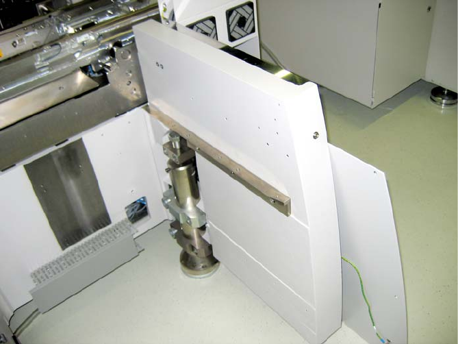
Fig. 2.6.1 For installation in prepared machine
00377312-xx
Retrofit kit interface comp
onent trolley HF
up to A001 left for location 1/3
00377313-xx
Retrofit kit interface comp
onent trolley HF
up to A001 right for location 2/4
Assembly instructions MTC2 and Component docking unit on SIPLACE HF and X-series
Edition 07/2009
81
2
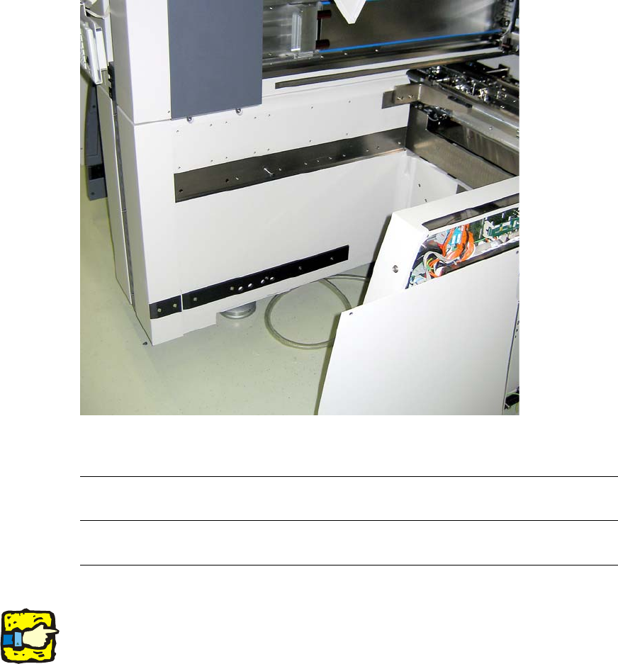
Fig. 2.6.2 For installation in prepared machine (inside)
2
2
2
Prior to installation of the component docking unit, ensure that the tape cutter control PCB is
coded for the correct location (see jumper marking on control PCB). For further information, see
imprint on tape cutter control PCB. 2
2
2
2
2
2
2
2