00193897-0302_AI_MTC2+BE_DE+EN.pdf - 第111页
Assembly instructions MTC2 and Component docking unit on SIPLACE HF and X-series Edition 07/2009 109 : Route the cables and hoses in the cable duct. : S tow the overhang including connectors and couplings in the open ing…

Assembly instructions MTC2 and Component docking unit on SIPLACE HF and X-series
Edition 07/2009
108
2
Tab. 2.8 - 1 Component docking unit: Connectors SIPLACE X-series
2
2
2
2
2
2
2
2
2
2
2
2
SIPLACE X-series
Cable harness component docking unit
X-tape feeders (03021067-)
Location 1 Location 2 Location 3 Location 4
FCU / Unlock device / Tape cutter / Option
(nozzle changer / reject bin sensor)
Power
X2*1
03020610-
X111
03002491-
X121
03002492-
X131
03002493-
X141
03002494-
FCU docking unit control
X2*5
03021069-
X215
03021071-
X225
03021072-
X235
03021073-
X245
03021074-
Component signalling
(location addressing /
control unit tape cutter)
X1*2
03019056-
X112
03002541-
X122
03002530-
X132
03002534-
X142
03002546-
Safety
(safety switch)
X1*3 / X2*3
03019057-
X113
03002542-
X123
03002531-
X133
03002535-
X143
03002547-
CAN bus / 1 wire (in)
X1*5
03019058-
X115
03010051-
X125
03010053-
X135
03010054-
X145
03010052-
CAN bus / 1 wire (out)
X1*6
03019058-
X116
03010050-
X126
03010054-
X136
03010059-
X146
03010051-
Docking unit valve on/off
X2*4
03021030-
X2fn
03017446-
X2gn
03017447-
X2hn
03017448-
X2kn
03017449-
Pneumatic supply bulk 03004200- 03004679- 03004679- 03004679- 03004679-
Option: Patch cable for
1-wire CAT5 splitter
(nozzle changer + reject bin
sensor)
X4*k
X4rk
03041627-
X4qk
03041627-
X2qk
03041628-
X2rk
03041628-
Assembly instructions MTC2 and Component docking unit on SIPLACE HF and X-series
Edition 07/2009
109
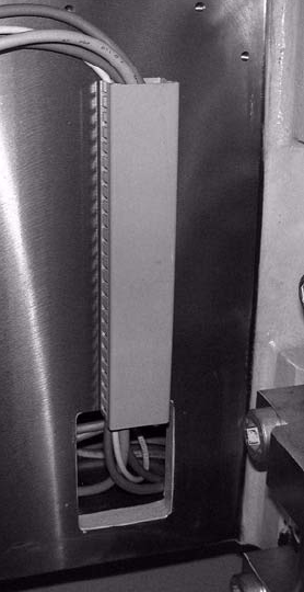
: Route the cables and hoses in the cable duct.
: Stow the overhang including connectors and couplings in the opening in the machine frame.
: Fit the side covers of the machine frame.
2
Fig. 2.8.3 Cable duct and opening in machine frame
Assembly instructions MTC2 and Component docking unit on SIPLACE HF and X-series
Edition 07/2009
110
2
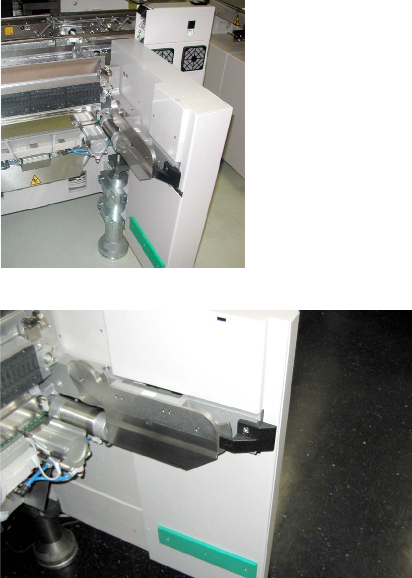
Fig. 2.8.4 Component docking unit in 1-gantry placement area
2
Fig. 2.8.5 Component docking unit in the 2-gantry placement area
2