00193897-0302_AI_MTC2+BE_DE+EN.pdf - 第112页
Assembly instructions MTC2 and Component docking unit on SIPLACE HF and X-se ries Edition 07/2009 110 2 Fig. 2.8.4 Component docking unit in 1-gantry placement area 2 Fig. 2.8.5 Component docking unit in the 2-gantry pla…
Assembly instructions MTC2 and Component docking unit on SIPLACE HF and X-series
Edition 07/2009
109
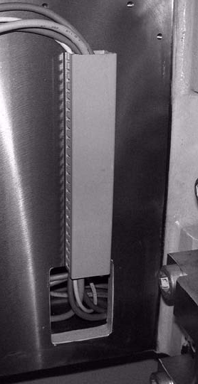
: Route the cables and hoses in the cable duct.
: Stow the overhang including connectors and couplings in the opening in the machine frame.
: Fit the side covers of the machine frame.
2
Fig. 2.8.3 Cable duct and opening in machine frame
Assembly instructions MTC2 and Component docking unit on SIPLACE HF and X-series
Edition 07/2009
110
2
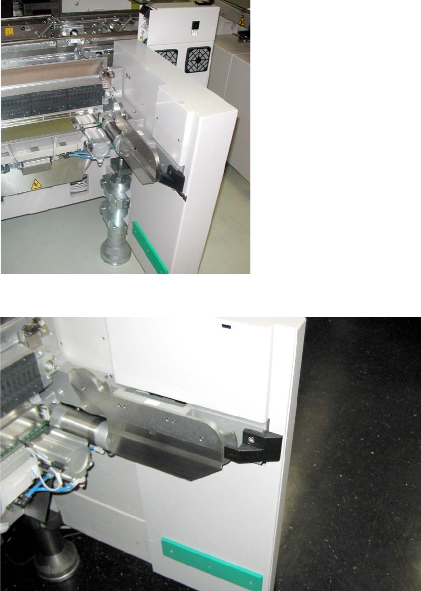
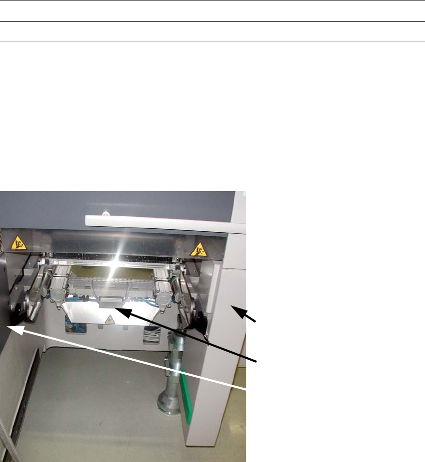
Fig. 2.8.4 Component docking unit in 1-gantry placement area
2
Fig. 2.8.5 Component docking unit in the 2-gantry placement area
2
Assembly instructions MTC2 and Component docking unit on SIPLACE HF and X-series
Edition 07/2009
111
If provided, mount the nozzle changer and reject bin sensors. For further information, see the
latest instructions: 2
00194482-xx Assembly instructions nozzle changer SIPLACE X-series
00194716-xx Assembly instructions reject bin sensors SIPLACE X-series
2
2
Mount parts from retrofit kit
The following parts must be mounted or fitted. 2
1. Cover long EGS centre
2. Machine cover X-F cover cpl. /
Machine cover X-S cover cpl.
3. Wasteþchute
Machine cover plate
X-F or X-S
Wasteþchute
Cover long EGS centre
2
Fig. 2.8.6 Installed retrofit kit
2
: Fit the cover over the pneumatic unit or power supply.