00193897-0302_AI_MTC2+BE_DE+EN.pdf - 第139页
Assembly instructions MTC2 and Component docking unit on SIPLACE HF and X-series Edition 07/2009 137 2.13.1 Conversion of light barriers MTC2 in combination with a C&P 6/12 / CPP 2 Crash risk: If an MTC2 is operated …
Assembly instructions MTC2 and Component docking unit on SIPLACE HF and X-series
Edition 07/2009
136
– Crash risk: When the CPP head is used with the MTC, the "notched base“ positioning aid on
the pull-out frame of the MTC must also be replaced. You should therefore fit 2 x item no.:
03010773-02 "Notched base“ (height: 103 mm). These are included in the package.
– A pull-out frame with the FS04 does not require further conversion.
MTC notched
base (standard)
2
2
– When the CPP head is used with the MTC, the crash light barriers on the MTC's feed axis must
be fitted in the bottom position. Read the "MTC2 on component trolley docking unit X-S" as-
sembly instructions (item no. 00194725-xx).
– If the CPP is in the high position in conjunction with the MTC
, the lowest pick-up height is 1.5
mm from the top edge of the PCB when the shortest nozzle (9 mm) is used. Interference edges
on the trays should also be taken into account.
2
2
2
2
Assembly instructions MTC2 and Component docking unit on SIPLACE HF and X-series
Edition 07/2009
137
2.13.1 Conversion of light barriers MTC2 in combination with a C&P 6/12 / CPP
2
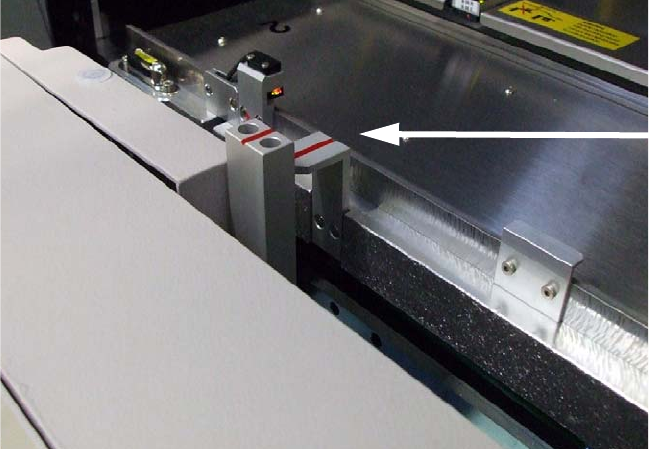
Crash risk: If an MTC2 is operated in a location or placement area with C&P6/12, the top light
barrier must be brought into the parked position for high components, otherwise there is a risk of
a head crash. 2
: Loosen the screw on the top light barrier (transmitter and receiver) on tower 1.
Light barrier:
prior to modification and
mounted in parked position
2
Fig. 2.13.1 Top light barrier on MTC2
2
2
Assembly instructions MTC2 and Component docking unit on SIPLACE HF and X-series
Edition 07/2009
138
2
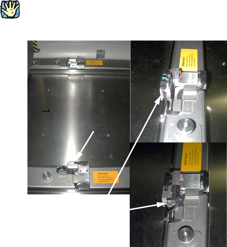
Both the transmitter and receiver must be mounted in the parked position.
2
2
: Fix the light barrier in the parked position.
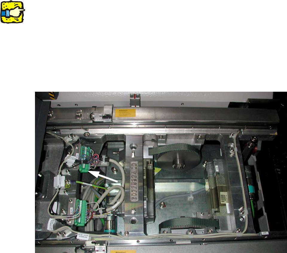
: Remove the plate over the connectors on tower 1.
: Remove the contacts 13 (brown) and 14 (black) on connector XS43.
: Insulate both cable ends.
2
Fig. 2.13.2 Stecker X43
2
2
2
2
2
2
2
2
2