00193897-0302_AI_MTC2+BE_DE+EN.pdf - 第105页
Assembly instructions MTC2 and Component docking unit on SIPLACE HF and X-series Edition 07/2009 103 2.8 Inst allation of component docking unit for X-t ape feeders on a SIPLACE X-series 2 This component docking unit is …
Assembly instructions MTC2 and Component docking unit on SIPLACE HF and X-series
Edition 07/2009
102
Mount parts from retrofit kit
: The following parts must be mounted or fitted:
1. Cover long EGS centre
2. Barcode foil X sector 2 or barcode foil X sector 4
3. Machine cover X-F cover cpl./
Machine cover X-S cover cpl./
4. Protection X-HS R barcode panel cpl.
5. Wasteþtape chute
2
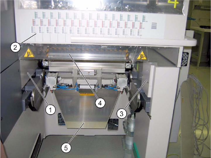
Fig. 2.7.5 SIPLACE HF location 2/4 (1-gantry placement area).
2
: Fit the cover over the pneumatic unit or power supply.
2
Assembly instructions MTC2 and Component docking unit on SIPLACE HF and X-series
Edition 07/2009
103
2.8 Installation of component docking unit for X-tape
feeders on a SIPLACE X-series
2
This component docking unit is not approved for HF and D3.
00378465-xx Retrofit kit component docking unit X
2
2
2
2
Prior to installation of the component docking unit, ensure that the tape cutter control PCB is
coded for the correct location (see jumper marking on control PCB). For further information, see
imprint on tape cutter control PCB. 2
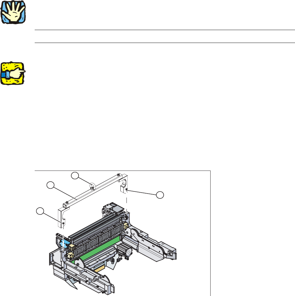
: Mount the fit-up aid (2) on
the fasteners (1) provided on the component docking unit.
: Attach the lifting device to the eye (3) of the fit-up
aid (2).
2
1. Fixing
2. Fit-up aid f. carriage or entering /X-S (03015976-)
3. Eye
1
1
3
2
2
2
2
Assembly instructions MTC2 and Component docking unit on SIPLACE HF and X-series
Edition 07/2009
104
2
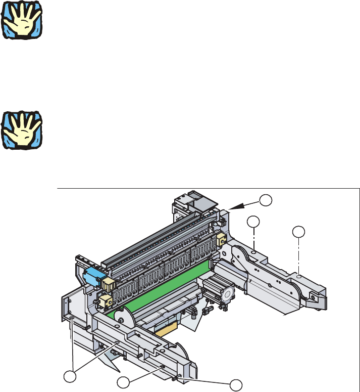
Heavy machine component:
The component docking unit is very heavy. For lifting purposes, the fit-up aid and suitable lifting
equipme
nt must be used (hand crane, etc.). 2
: Suitable gloves must be worn for lifting the
component docking unit in position.
Gloves reduce the risk of cuts caused by the bla
de of the tape cutter.
: Lift the component docking unit out of the machine with
the aid of the lifting device.
2
Ensure that the cables and hoses are not damaged. 2
2
: Remove the fit-up aid12.
1
1
3
1
1
2
2
: Push the component docking unit into the correct position. See diagram ‘Assembly positions
according to machine type and location’.
2