ACT - Accuracy Check Tool mit SSW 6xx User Manual 2017.pdf - 第94页
ACT with SSW 6xx / User Manual 07/2017 Edition 30 4.1.2 Specifying the Boards ► Select a suiting pla cement program for your head configurat ion from t he pre - configured boards (with th e aid of Table 4-1 or Table 4-2 …

ACT with SSW 6xx / User Manual 07/2017 Edition
29
4.1.1.2 Placement Program Overview for SIPLACE Pro ≥ 11.x
Station software version 706.02.SP1 Hotfix 2 or 707.1.SP1 Hotfix 2 or higher
Machine Head Camera Nozzle Placement program
X-series;
CAx
with SW 605.xx
1 x C&P20x
SST 23,
SST 41
1004 / 1014 /
4004
ACT_1xC&P20
(80 x Cerampad)
2 x C&P20x
ACT_2xC&P20
(2 x 80 x Cerampad)
4 x C&P20x
ACT_2xC&P20
(4 x 80 x Cerampad)
X-/D-series
1 x C&P12-DLM,
1 x CPP
(C&P mode)
SST 28,
SST 29,
SST 30,
SST 38
904 / 914
ACT_1xC&P12
(96 x Cerampad)
2 x C&P12-DLM,
2 x CPP
(C&P mode)
ACT_2xC&P12
(2 x 96 x Cerampad)
D-/X-series and
CAx
with SW 605.xx
C&P6
SST 29,
SST 30
920
ACT_CC02-05
(48 x CC02-05)
X-/D-series
TH-IC,
P&P-IC
SST 33,
SST 36
518
ACT_CC02-05_PP
2)
(48 x CC02-05)
X-/D-series
TH-IC,
P&P-IC
SST 33,
SST 36
518
ACT_CC02-05_CPP_TH
4)
(48 x CC02-05)
X-/ D-series
TH-IC,
P&P-IC
SST 25 518
ACT_CC02-05_FC
1)
(48 x CC02-05)
E by SIPLACE
3)
1 x C&P14
SST 23,
SST 41
4004
ACT_1xC&P14
(112 x Cerampad)
Table 4-2: Assignment of machine, board, head as of SIPLACE Pro 11.x
1)
As of software SIPLACE Pro 11.x with station software version 706.02.SP1 Hotfix 2 or 707.1.SP1 Hotfix 2 or higher,
the CC02-05 component (with QFP structure) is used for the SST 25 camera (Flip-Chip camera)..
The CC07-500 glass component (with BGA structure) is not supported anymore.
If the CC07-500 component is already available and still to be used for measuring the SST 25 camera, the
corresponding board with its component and component shape data and the tables can be selectively imported from
the *.sipro files of the SIPLACE Pro 9 version. This data can be obtained from the Software License Portal or via the
hotline.
2)
As of software SIPLACE Pro 11.x with station software version 706.02.SP1 Hotfix 2 or 707.1.SP1 Hotfix 2 or higher.
From this version, a separate board description is available for all Pick & Place heads in which the CPP head has now
been integrated for the P&P mode.
3)
Machine type E by SIPLACE, as of station software version 708.0. Listed in the table because the board is created with
the SIPLACE Pro import. However, a CPP head cannot be used with station software 6xx.
4)
For compatibility with older station software versions.
If SIPLACE Pro has been updated without updating the station software, the machine verification of CPP heads in P&P
mode can be performed anyway with this program.
ACT with SSW 6xx / User Manual 07/2017 Edition
30
4.1.2 Specifying the Boards
► Select a suiting placement program for your head configuration from the pre-configured boards
(with the aid of Table 4-1 or Table 4-2).
► Specify a job (recipe) in SIPLACE Pro Line Control and send it to the line (download).
NOTICE
Placement machines with dual conveyors
When using a dual conveyor, the ACT should be run with both conveyor lanes.
4.1.2.1 Accessibility problems for various machine / head configurations
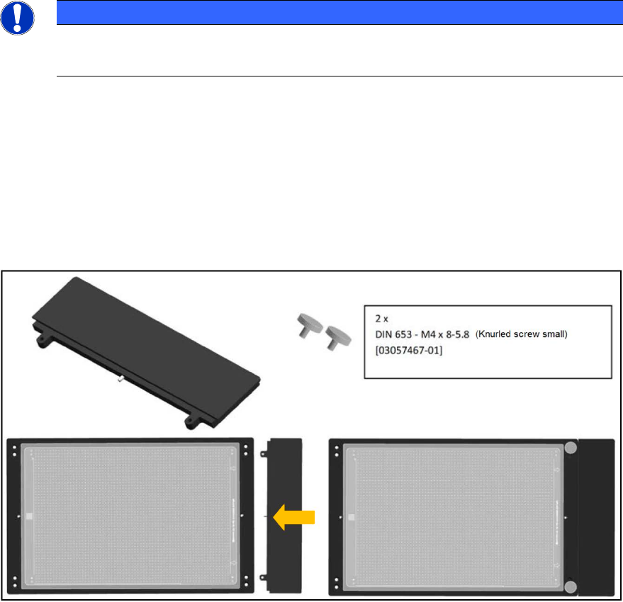
Twin Head in Placement Area 1:
For machines with Twin Head in placement area 1 (i.e. gantry 1 and / or 4), you can use the
following adapter to ensure the accessibility of segment 2 during placement on the plate. The
adapter is placed on the front of the plate to move the plate by a total of 50 mm to the rear in the
direction of the input belt.
50 mm TWIN adapter [03085310-01]
Figure 4-1: 50 mm TWIN adapter
ACT with SSW 6xx / User Manual 07/2017 Edition
31
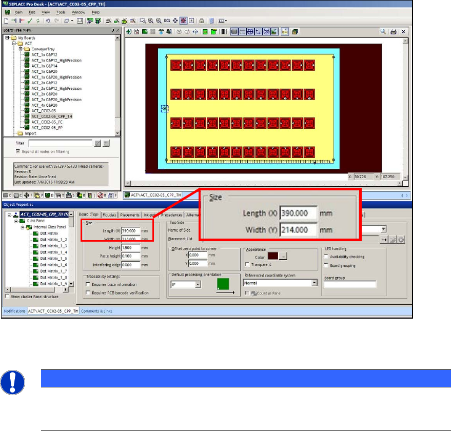
If you use the "50 mm TWIN adapter" [03085310-01] in the outmost panel, you must extend the
board by 50 mm in SIPLACE Pro Desk!
► For this, enter 390 mm length instead of 340 mm in the board description that you want to use
(ACT_CC02-05_CPP_TH).
Figure 4-2: Extending the board
Twin Head – statistical reliability:
NOTICE
► When measuring a Twin Head, pay attention to the number of placed components
per segment to ensure the statistical reliability of the measurement result.
At least 20 components per segment should be placed!
With the setup of the tray with the glass components, pickup problems may occur for some
machine types because the components cannot be reached.
► Pay attention to the tray position on the component table or in the WPC.
Variants:
► By positioning the tray on the BE table, ensure that the components can be reached in X-
direction from both segments.
As soon as the two front rows are empty:
► Stop the machine.
► Refill the components at the front.
► Set the filling level to "Full" again.
This also applies for the tray setup in the WPC. The components have to be refilled in the WPC
too (e.g. WPC at the SX1/2 machine) to ensure that a sufficient number of components can be
picked up by both Twin segments.