SOM-1802-002_w.pdf - 第23页
20 AJBES-P 4.2.5 (B01) Shape Data All component shapes are expressed based on the following packaged condition. Fig. 6 T op View of Packaged Components (B01_02) Mold size (1) X [mm] (Horizontal) and Y [mm] (V ertical) Se…
19 AJBES-P
4.2 Data Explanation (A03_01), (A03_02), (A03_03), (A03_04), (A03_05),(A04_01)
0606-002
4.2.3 (A03) Carrier Data
(A03_01) Carrier Data
Refer to "Component Library for GXH Series" in the instruction manual
for details.
(A03_02) Tape end detection
Refer to "Component Library for GXH Series" in the instruction manual
for details.
(A03_03) Tray Data
Refer to "Component Library for GXH Series" in the instruction manual
for details.
(A03_04) Shuttle tray data
Refer to "Component Library for GXH Series" in the instruction manual
for details.
(A03_05) Stick data
Refer to "Component Library for GXH Series" in the instruction manual
for details.
4.2.4 (A04) Placeable Data
(A04_01) Machine Name
Refer to "Component Library for GXH Series" in the instruction manual
for details.
Reference
Reference
Reference
Reference
Reference
Reference
20 AJBES-P
4.2.5 (B01) Shape Data
All component shapes are expressed based on the following packaged
condition.
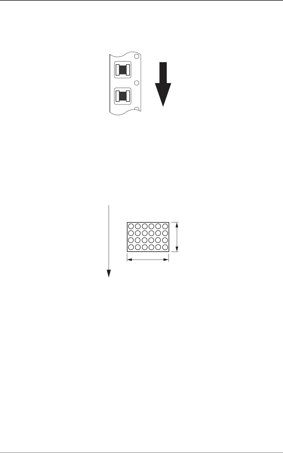
Fig. 6 Top View of Packaged Components
(B01_02) Mold size
(1) X [mm] (Horizontal) and Y [mm] (Vertical)
Set Dimensions X and Y of the molded section.
Area Array
Fig. 7
0606-002
BGA
X
Y
Top View of Component
User Direction of Feed
4.2 Data Explanation (B01_02)
21 AJBES-P
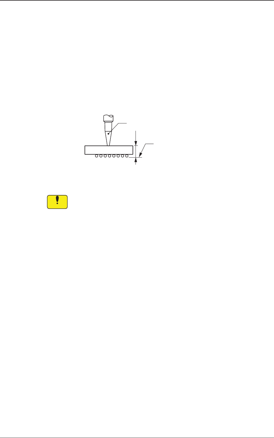
(2) T [mm] (thickness), t [mm] (thickness), and Ut [mm]
(thickness)
Set the thickness of the component in these text boxes.
T (Thickness) : Thickness between Component Placement and
Uppermost Surfaces
t (Thickness) : Thickness between Component Placement and
Nozzle Pickup Surfaces
Ut (Thickness) : Thickness between Component Lowermost and
Placement Surfaces
Fig. 8
When values different from the actual component thickness are set
in the "T [mm]", the "t [mm]", and/or the "Ut [mm]" text box of the
label "Mold size", there is a possibility that the picked components
may interfere with the previously-placed components, the PCB
chute, etc.
T=t
Ut=0
Vacuum Nozzle
Component
Placement
Surface
0606-002
4.2 Data Explanation (B01_02)
Notice