SOM-1802-002_w.pdf - 第44页
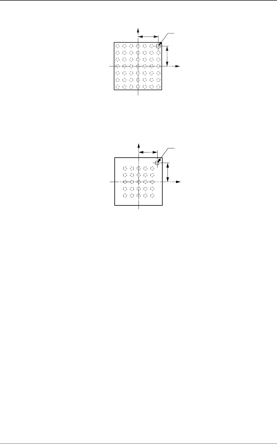
41 AJBES-P (3) Polarity position X [mm], Y [mm] Set the distances between the centers of the mold and the inspection range. Fig. 28 T o set parameters in these text boxes, "Enable (Discard)" or "Enable (Pl…
40 AJBES-P
Example: Regarding the missing ball as a polarity
Fig. 25
Example: Regarding the mark on the mold as a polarity
Fig. 26
4.2 Data Explanation (B02_15)
X(+)
Y(+)
Inspection
Range
Top View of Component
X(+)
Y(+)
Inspection Range (Mark)
Top View of Component
0606-002
41 AJBES-P
(3) Polarity position X [mm], Y [mm]
Set the distances between the centers of the mold and the inspection
range.
Fig. 28
To set parameters in these text boxes, "Enable (Discard)" or "Enable
(Placement)" must be selected in the "Polarity detn" text box.
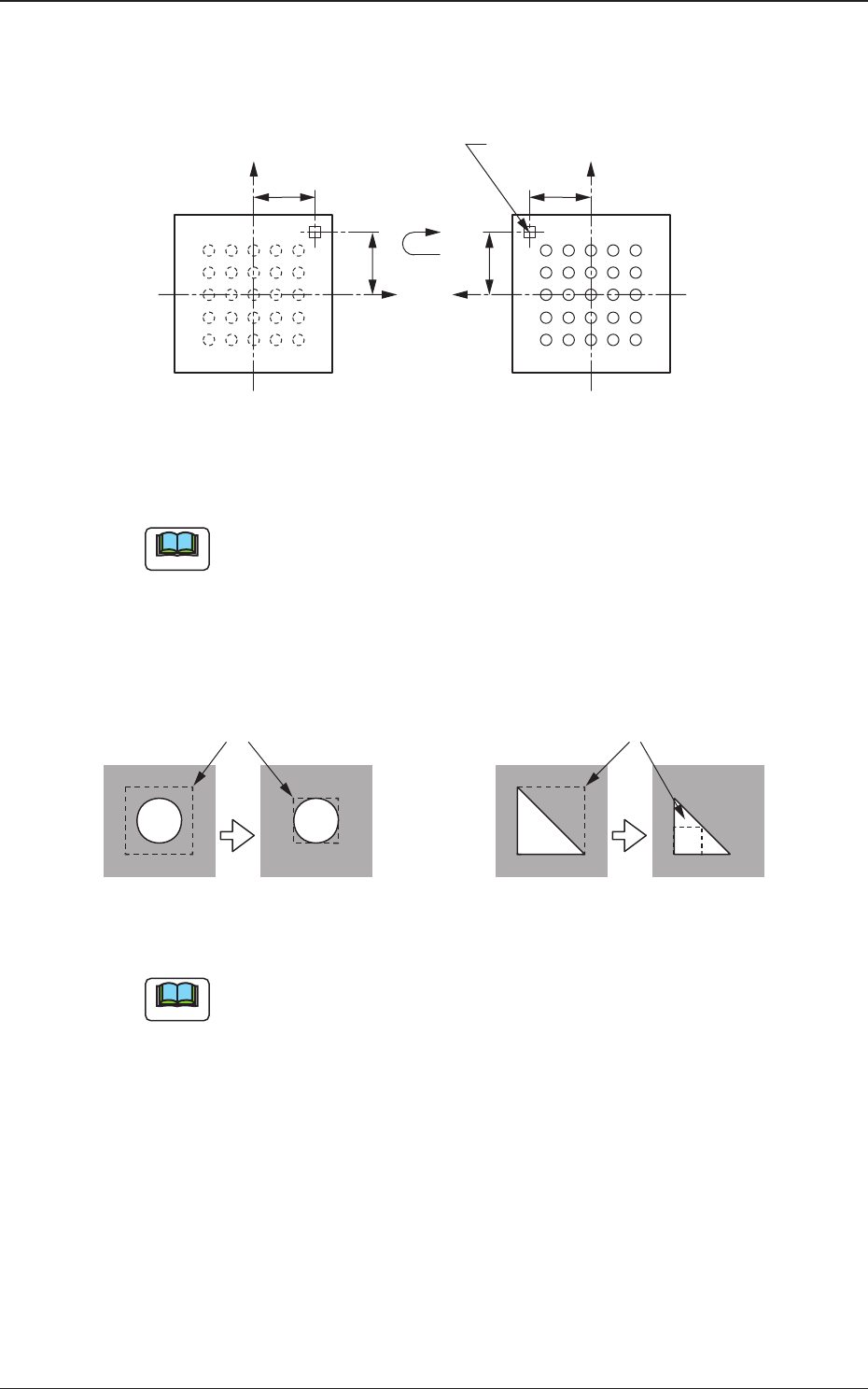
(4) Inspection range [mm]
Specify the range to be inspected.
Fig. 29
(a) Set a parameter as an inspection range such that the range having
high contrast is narrowed.
The threshold levels in the inspection range will increase or
decrease, making it easy to determine the polarity.
(b) To set a parameter in this text box, "Enable (Discard)" or "Enable
(Placement)" must be selected in the "Polarity detn" text box.
4.2 Data Explanation (B02_15)
X(+)
Y(+)
X(+)
Y(+)
Bottom View of Components
(Ball Side)
Inspection Range (Mark)
Top View of Component
Note
Note
Inspection Range
Impossible Possible
Threshold = 50 Threshold = 100
Inspection Range
Impossible Possible
Threshold = 50 Threshold = 100
0606-002
42 AJBES-P
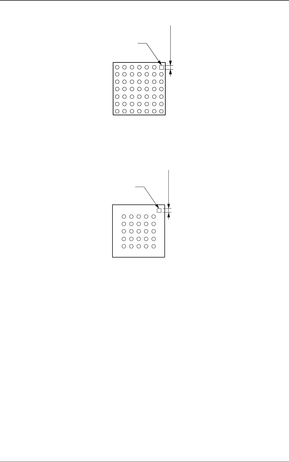
Example: Regarding the missing ball as a polarity
Fig. 30
Example: Regarding the mark on the mold as a polarity
Fig. 31
4.2 Data Explanation (B02_15)
Top View of Component
Inspection
Range
Mark
Top View of Component
Mark
Inspection
Range
0606-002