SOM-1802-002_w.pdf - 第24页
21 AJBES-P (2) T [mm] (thickness), t [mm] (thickness), and Ut [mm] (thickness) Set the thickness of the component in these text boxes. T (Thickness) : Thickness between Component Placement and Uppermost Surfaces t (Thick…
20 AJBES-P
4.2.5 (B01) Shape Data
All component shapes are expressed based on the following packaged
condition.
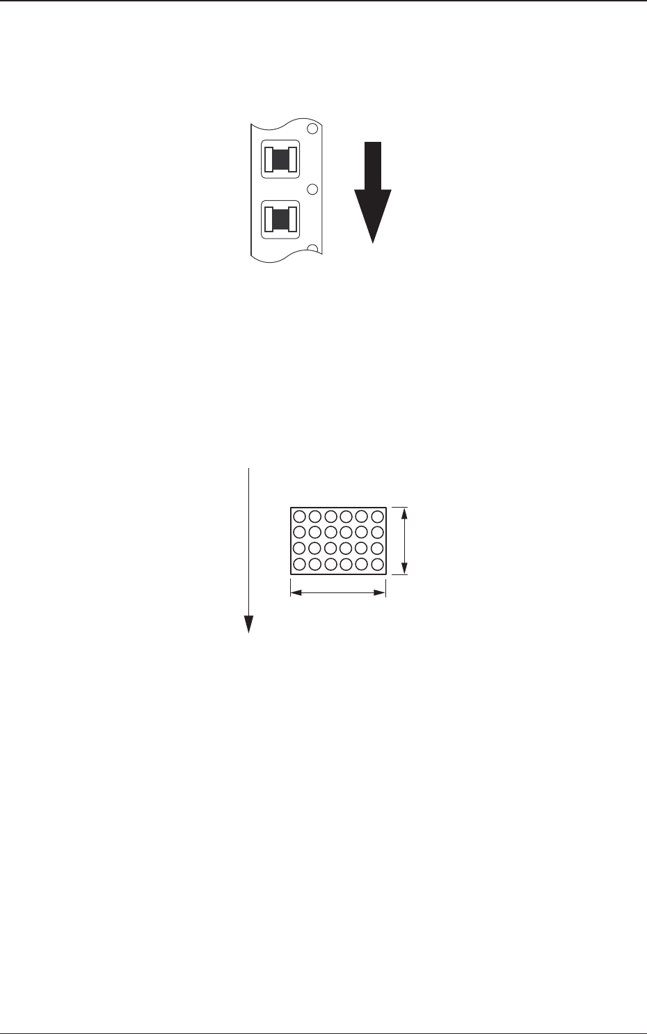
Fig. 6 Top View of Packaged Components
(B01_02) Mold size
(1) X [mm] (Horizontal) and Y [mm] (Vertical)
Set Dimensions X and Y of the molded section.
Area Array
Fig. 7
0606-002
BGA
X
Y
Top View of Component
User Direction of Feed
4.2 Data Explanation (B01_02)
21 AJBES-P
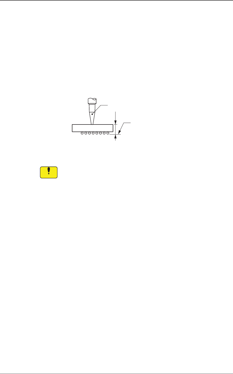
(2) T [mm] (thickness), t [mm] (thickness), and Ut [mm]
(thickness)
Set the thickness of the component in these text boxes.
T (Thickness) : Thickness between Component Placement and
Uppermost Surfaces
t (Thickness) : Thickness between Component Placement and
Nozzle Pickup Surfaces
Ut (Thickness) : Thickness between Component Lowermost and
Placement Surfaces
Fig. 8
When values different from the actual component thickness are set
in the "T [mm]", the "t [mm]", and/or the "Ut [mm]" text box of the
label "Mold size", there is a possibility that the picked components
may interfere with the previously-placed components, the PCB
chute, etc.
T=t
Ut=0
Vacuum Nozzle
Component
Placement
Surface
0606-002
4.2 Data Explanation (B01_02)
Notice
22 AJBES-P
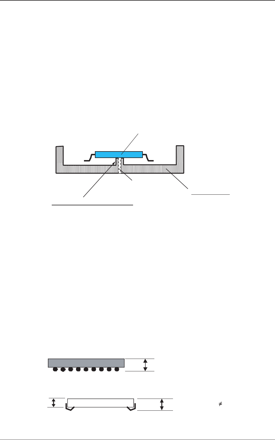
(3) Mt (Mold thickness) [mm]
When the shuttle tray feeder is used, the component thickness data
(Mt (Mold thickness)) is added to the shape data.
The components are loaded onto the saucer stage in the shuttle
section after they are picked up through the P&P motion of the shuttle
tray feeder. After that, the saucer stage is transferred (shuttled) to the
main machine and the components are picked up on the main machine
side.
Several lower holding sections (protrusions) are set up on this saucer
stage to temporarily fasten the loaded components.
Fig. 8-1
No stress should be imposed on a component when the component is
loaded onto the saucer stage in the shuttle section after being picked
up from the tray with the P&P pad of the shuttle tray feeder.
In this case, component thickness other than "t", "Ut", and "T" speci-
fied already in the "Mold size" data is required for the amount of the
P&P-L axis downward movement.
Therefore, new component thickness data (mold thickness) is pre-
pared as "Mt" for the shuttle data.
Fig. 8-2
Component
Saucer Stage
Protrusions for Lower Holding:
These protrusions are used to make a difference in the
levels between the saucer stage and the component,
so that no stress can be imposed on the component leads.
Vacuum Path for
Lower Holding
t
tT Mt
TMt
t
Mt
Example 1: In the case of BGA components, Values "t",
"T", and "Mt" must be the same.
Example 2: In the case of PLCC components,
Value "t" equals to "T" but Value "Mt" must be different.
=
=
=
0606-002
4.2 Data Explanation (B01_02)