SOM-1802-002_w.pdf - 第36页
33 AJBES-P 4.2.6 (B02) Recognition Data (B02_01) Lighting system "Front Ltg System" is selected as a lighting system for component recognition. (B02_02) Recognition data set Select one of the following options …
32 AJBES-P
(7) # of Missing
Set the number of missing blocks.
When some electrodes are missing in the arrayed ones, the group of
electrodes is regarded as a block (a group of missing electrodes) and
the number of blocks can be specified.
• Data Input Range
0 to 40
(a) The above parameters must be specified when "BGA/CSP (Simple)"
is selected.
(b) The blocks can be stacked upon each other.
(c) When the number of missing blocks is set, "Missing Stg Row",
"Missing Stg Col", "# of Missing Rows [pcs.]", and "# of Missing
Cols [pcs.]" are displayed.
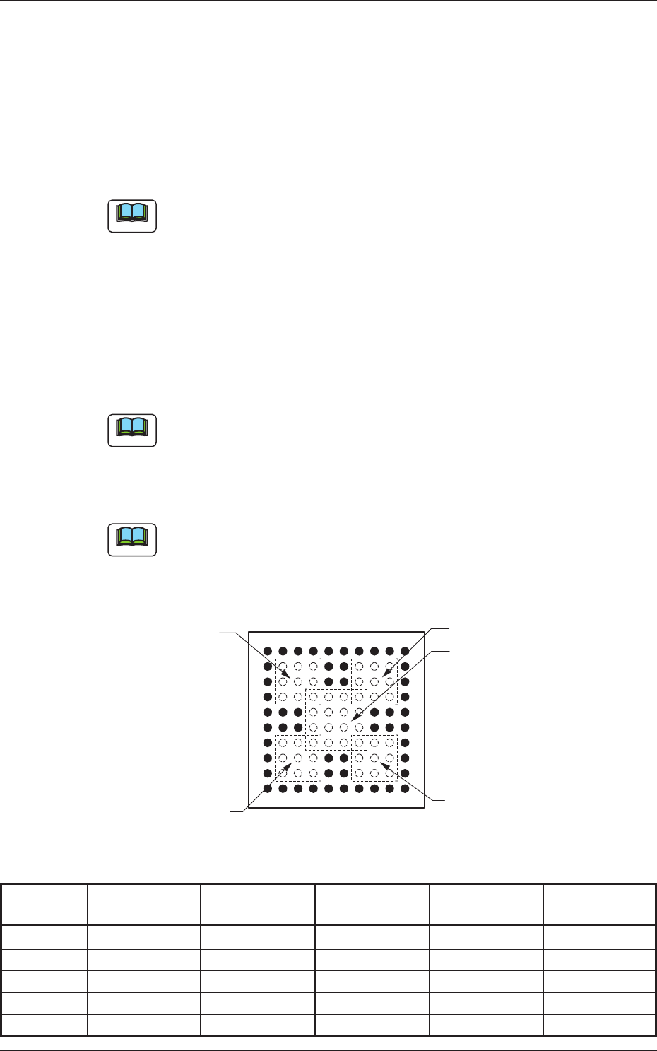
(8) Missing Stg Row and Missing Stg Col
Set the row and column Nos. from which the missing electrode block
starts.
The above parameters must be specified when "BGA/CSP (Simple)" is
selected.
(9) # of Missing Rows [pcs.] and # of Missing Cols [pcs.]
Set the number of missing rows and columns.
The above parameters must be specified when "BGA/CSP (Simple)" is
selected.
Fig. 19
Table 10
Electd Grp Missing Elctd Missing Stg Missing Stg # of Missing # of Missing
No. No. Row Col Rows Cols
1 1 002 002 003 003
1 2 007 002 003 003
1 3 007 007 003 003
1 4 002 007 003 003
1 5 004 004 004 004
Note
0606-002
4.2 Data Explanation (B01_15)
10
9
8
7
6
5
4
3
1
2
61543210
98
7
Example:
Missing Block 1
Column
Row
Top View of Component
Missing Block 2
Missing Block 4
Missing Block 5
Missing Block 3
Note
Note
33 AJBES-P
4.2.6 (B02) Recognition Data
(B02_01) Lighting system
"Front Ltg System" is selected as a lighting system for component
recognition.
(B02_02) Recognition data set
Select one of the following options to specify whether the recognition data
related to each individual component shapes should be set automatically or
manually.
Auto : The defaults (determined in advance) are automatically set.
Manual : Each recognition data can be set manually.
(a) Select "Auto" in normal cases.
(b) When "Auto" is specified in the "Recognition data set" text box,
each parameter is automatically set as follows.
The specified parameters in the table (the parameters specified when
"Auto" is selected) are defined individually in this manual (each data
item).
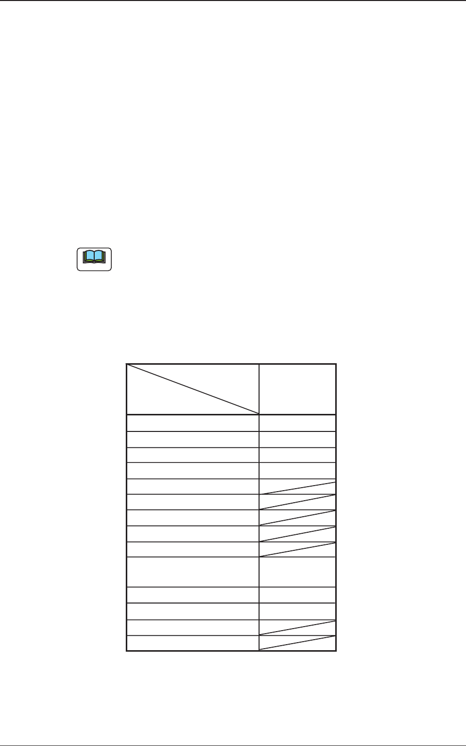
Table 11
Component Shape
BGA/CSP
Data Items
Brightness data des 0
Recognition level Standard
Front/Back ltg recog algo Auto
Lighting pattern Auto
Mold size tol Set
Lead width detn
Lead posn (Latl dir) detn
Lead posn (Long dir) detn
Outward length detn
Electd pos detn Enable
(Auto)
Electd size detn Disable
Polarity detn Disable
Image capture method
Shape pos detn
(B02_03) Brightness data des (Not available)
The following can be selected.
Standard : The standard data is selected.
4.2 Data Explanation (B02_01), (B02_02), (B02_03)
0606-002
Note
34 AJBES-P0606-002
4.2 Data Explanation (B02_04), (B02_05)
(B02_04) Recognition level
Set a recognition level for component checking.
Set "0" in normal cases.
• Data Input Range
00 to 99
(a) When "1" or a larger number is set, "Manual" should be selected in
the "Recog data set" text box.
(b) The following shows the contents of Recognition Level 1 or higher.
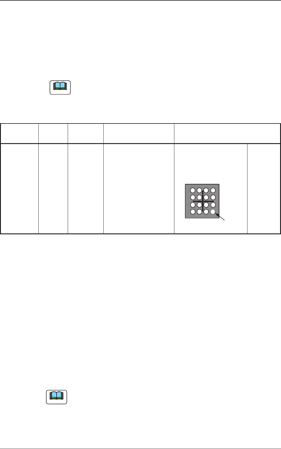
Table 12
Component
Algorithm
Processing
Description Sample Application
Shape Level
Area Array Grid 1
(BGA) Pattern
(B02_05) Front ltg recog algo
Specify a recognition mode.
Grid Pattern:
When "BGA/CSP (Simple)" is selected, this recognition mode can be
specified.
The electrodes consisting of meshes (grids), the bumps, etc., can be
detected.
Multi Pattern:
When "BGA/CSP (Complex)" is selected, this recognition mode can be
specified.
The electrodes, bumps, etc., arranged at random can be detected.
To set a parameter, select "Manual" in the "Recog data set" text box.
Note
Positioning is performed,
using only the detected
balls.
(No Ball Detection)
Positioning is possible even
when some of the balls
cannot be detected due to
deformations, etc.
Undetected Ball
Note