SOM-1802-002_w.pdf - 第40页
37 AJBES-P (B02_13) Electd pos detn/Electd pos tol [mm] Select one of the following options to determine whether or not the electrode position should be detected. When "Enable (Auto)" or "Enable (Mnl)"…
36 AJBES-P
(3) Front ltg 1 (Ring (Dn))
When "Manual" is selected in the "Lighting pattern" text box, select
one of the following options ("On" or "Off") as the lighting pattern for
the lower ring lamp for the front lighting system.
(4) Front ltg 2 (Coax)
When "Manual" is selected in the "Lighting pattern" text box, select
one of the following options ("On" or "Off") as the lighting pattern for
the coaxial lamp for the front lighting system.
(5) Fron ltg 3 (Ring (Up))
When "Manual" is selected in the "Lighting pattern" text box, select
one of the following options ("On" or "Off") as the lighting pattern for
the upper ring lamp for the front lighting system.
(B02_07) Image capture method
Select one of the following options as a method to capture an image of
the picked component.
Disable : A proper method is automatically selected.
Single : The image of the component is
captured at the camera center position.
When the image is captured, the height
position of the nozzle end is regarded as an
element of no importance.
Single (Descent) : When an image is captured, the height
position of the nozzle end is kept at a
position lower than the underside of the
linear measure sensor.
This method should be taken for the area
array components, etc., that might be
interfered by the lighting linear measure
sensor.
To set a parameter, select "Manual" in the "Recog data set" text box.
4.2 Data Explanation (B02_06), (B02_07)
Note
0606-002
37 AJBES-P
(B02_13) Electd pos detn/Electd pos tol [mm]
Select one of the following options to determine whether or not the electrode
position should be detected. When "Enable (Auto)" or "Enable (Mnl)" is
selected, the tolerance must be specified.
Disable : Select this when the electrode position determination
should not be made.
Enable (Auto) : Select this to make the electrode position determina-
tion.
The automatically specified default is used as an
electrode position tolerance.
Enable (Mnl) : Select this to make the electrode position determina-
tion.
The arbitrarily specified value is used as an elec-
trode position tolerance.
(a) To set a parameter, select "Manual" in the "Recog data set" text box.
(b) When "Enable (Auto)" is selected in this text box, the value
indicated in the "Electd pos tol [mm]" text box is used.
(B02_14) Electd size detn/Electd size tol [mm]
Select one of the following options to determine whether or not the electrode
size should be detected. When "Enable (Auto)" or "Enable (Mnl)" is selected,
the tolerance must be specified.
Disable : Select this when the electrode size determination
should not be made.
Enable (Auto) : Select this to make the electrode size determination.
The automatically specified default is used as an
electrode size tolerance.
Enable (Mnl) : Select this to make the electrode size determination.
The arbitrarily specified value is used as an elec-
trode size tolerance.
(a) To set a parameter, select "Manual" in the "Recog data set" text box.
(b) When "Enable (Auto)" is selected in this text box, the value
indicated in the "Electd size tol [mm]" text box is used.
0606-002
Note
Note
4.2 Data Explanation (B02_13), (B02_14)
38 AJBES-P
(B02_15) Polarity detn (Reserved Data)
Specify how to determine the polarity (direction) of the component.
(1) Polarity detn
Select one of the following options to determine whether or not the
polarity detection should be made.
Disable : Select this when the polarity detection
should not be made.
Enable (Discard) : When the polarity is checked and
determined as a different one, select this to
regard the recognition as an error.
Enable (Placement) : After the polarity is checked and
determined, select this to re-perform the
recognition according to the determined
polarity.
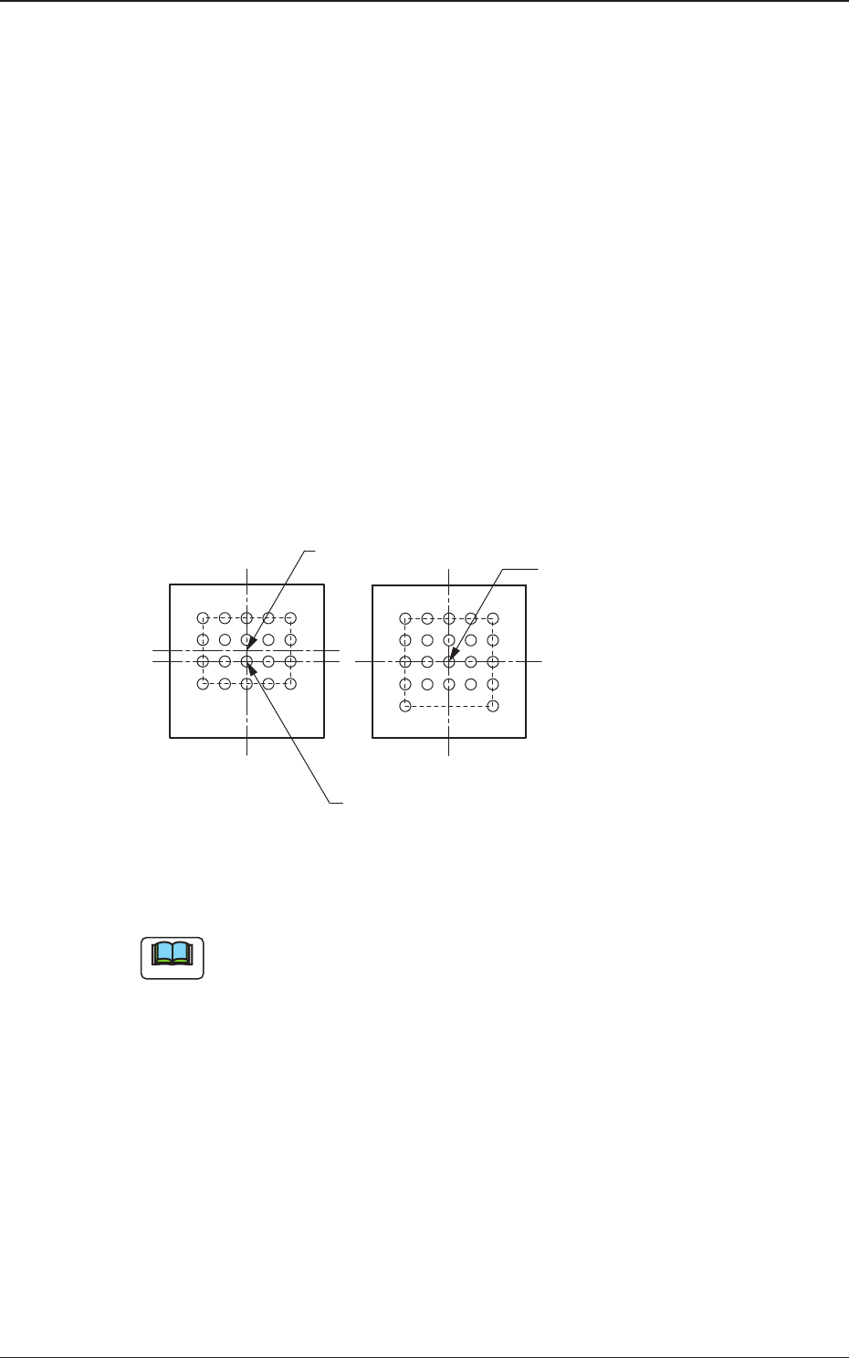
Fig. 21
(a) When "Enable (Placement)" is selected, the recognition processing
time becomes twice or more as long as the normal one.
(b) When it is required to check whether or not a component has a
polarity (when components are not fed in the specified direction),
"Enable (Discard)" or "Enable (Placement)" must be set in the text
box. The machine performs the recognition operation after checking
the polarity.
(c) The following requirements must be met when "Enable (Discard)" or
"Enable (Placement)" is selected.
• The center of the ball grids must be aligned perfectly with the
center of the mold.
Note
Top View of Component
Center of Ball Grids
Center of Ball Grids
Center of Mold
Center of Mold
Impossible
Possible
0606-002
4.2 Data Explanation (B02_15)