SOM-1802-002_w.pdf - 第31页
28 AJBES-P (3) # of Rows [pcs.], # of Cols [pcs.] Set the number of rows and columns in which the electrodes are arrayed. Fig. 13 (4) Row Pitch [mm], Col Pitch [mm] Set the pitches at which the electrodes are arrayed in …
27 AJBES-P
(B01_15) Electrode Group Data
The following parameters can be specified to classify some electrodes
into a group (s).
(1) Type No.
Set the electrode type data No. related to the specified group.
• Data Input Range
1 to 3
The above parameters must be specified when "BGA/CSP (Simple)" is
selected.
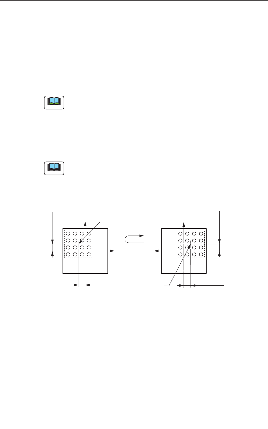
(2) Grp Posn X [mm], Y [mm]
Set the center position of the electrode group based on the center of
the mold.
(a) The above parameters must be specified when "BGA/CSP (Simple)"
is selected.
(b) As the center of the electrode group is located at the center of the
mold in normal cases, the coordinates X and Y become "0" (zero). (X,
Y = 0, 0)
Fig. 12
4.2 Data Explanation (B01_15)
0606-002
+Y
+Y
+X
+X
Position Y
Position X
Center of Electrode Group
Top View of Component Bottom View of Components
Center of Electrode
Group
Position X
Position Y
Note
Note
28 AJBES-P
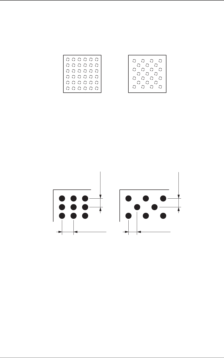
(3) # of Rows [pcs.], # of Cols [pcs.]
Set the number of rows and columns in which the electrodes are
arrayed.
Fig. 13
(4) Row Pitch [mm], Col Pitch [mm]
Set the pitches at which the electrodes are arrayed in each row and
column.
Fig. 14
4.2 Data Explanation (B01_15)
0606-002
6
15432
6
5
4
3
2
1
67
15432
7
6
5
4
3
2
1
"Checker" or "Reversed Checker"
Column Column
Row
Row
"Regular" or "Custom"
6 Rows and 6 Columns 7 Rows and 7 Columns
Top View of Component
Bottom View of Components
Row Pitch
Column Pitch
"Regular" or "Custom"
"Checker" or "Reversed Checker"
Row Pitch
Column Pitch

29 AJBES-P
(5) Insp Condtn
It can be determined how the set electrode group should be handled
for component positioning and inspection.
Select one of the following options.
Normal : The electrodes in the group are handled as
normal ones.
When this is selected, the pertinent
electrodes in the group are regarded as
object ones for inspections on positioning of
all components, cracks of electrodes, shape
of electrodes, etc.
Check of No Lead : When this is selected, the location of the
electrodes in the group is handled as
information of inspected spots where no
electrodes should exist.
When an electrode is detected in the
electrode spot to be registered in the group
under this inspection condition, the
component is discarded as one in which an
inspection error is caused.
In normal inspections, a cracked electrode is
regarded as an abnormal one. However, as
for extra electrodes, no checking is made.
This function is mainly used to discriminate
wrong components.
4.2 Data Explanation (B01_15)
0606-002