SOM-1802-002_w.pdf - 第27页
24 AJBES-P (3) Elctd type Select one of the following options as an electrode type. Ball : Select this when the electrode type is "Ball Grid Array". Land : Select this when the electrode type is "Land Grid…
23 AJBES-P
(B01_04) Component weight [mg]
Set the component weight in the text box.
(B01_05) Polarity existence
Set "Enable" or "Disable" to determine whether or not the component has a
polarity (direction).
This data is used for optimization of the pattern program.
Select "Enable" or "Disable".
(B01_13) Electrical Contact Data
Set the basic parameters related to the electrodes of the components.
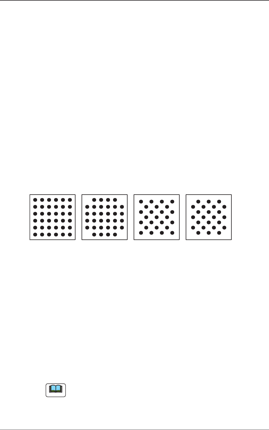
(1) Grid Type
Select one of the following grid types.
Regular : Regular Lattice
Custom : Lattice having no electrodes at 4 corners
Checker : Staggered Array
Reversed Checker : Reversed Staggered Array
Fig. 9
(2) Image
Select one of the following options depending on how the image of the
electrode is captured in comparison with the mold.
Bright : Select this when the captured image looks brighter than
the mold.
Dark : Select this when the captured image looks darker than the
mold.
(a) In normal cases, select "Bright".
(b) When the mold of a BGA component is made of ceramic, it might be
better to select "Dark".
Reversed CheckerRegular
Custom
Checker
Bottom View of Components
Note
0606-002
4.2 Data Explanation (B01_04), (B01_05), (B01_13)
24 AJBES-P
(3) Elctd type
Select one of the following options as an electrode type.
Ball : Select this when the electrode type is "Ball Grid Array".
Land : Select this when the electrode type is "Land Grid Array".
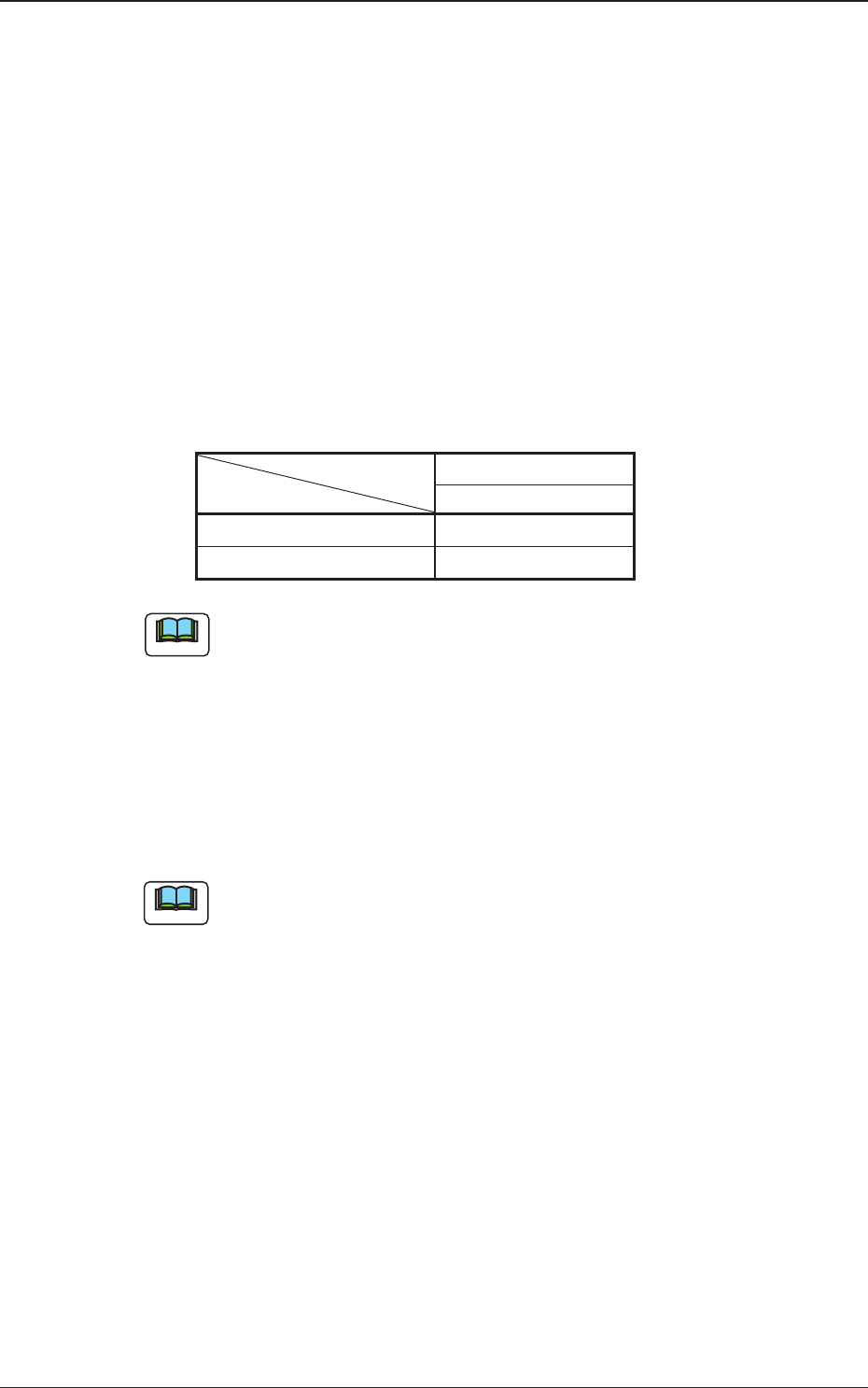
(4) Extended setting
Select "Enable" or "Disable" to determine whether or not the extended
data should be used.
When "Enable" is set in the "Extended setting" text box, the extended
data such as information on missing electrodes can be specified.
The following shows the extended data that can be specified.
Table 9
Area Array
BGA/CSP (Simple)
# of types {
Missing Elctd Set {
The above parameters must be specified when "BGA/CSP (Simple)" is
selected.
(5) # of types
Set the number of electrode types in the text box.
• Data Input Range
1 to 3
(a) The above parameters must be specified when "BGA/CSP (Simple)"
is selected.
(b) When several types are specified, it becomes possible to handle
such components that have electrodes of different diameters.
Note
Note
4.2 Data Explanation (B01_13)
0606-002
25 AJBES-P
(6) # of groups
Set the number of electrode groups in the text box.
• Data Input Range
BGA/CSP (Simple) : 1 to 30
BGA/CSP (Complex): 1 to 2000
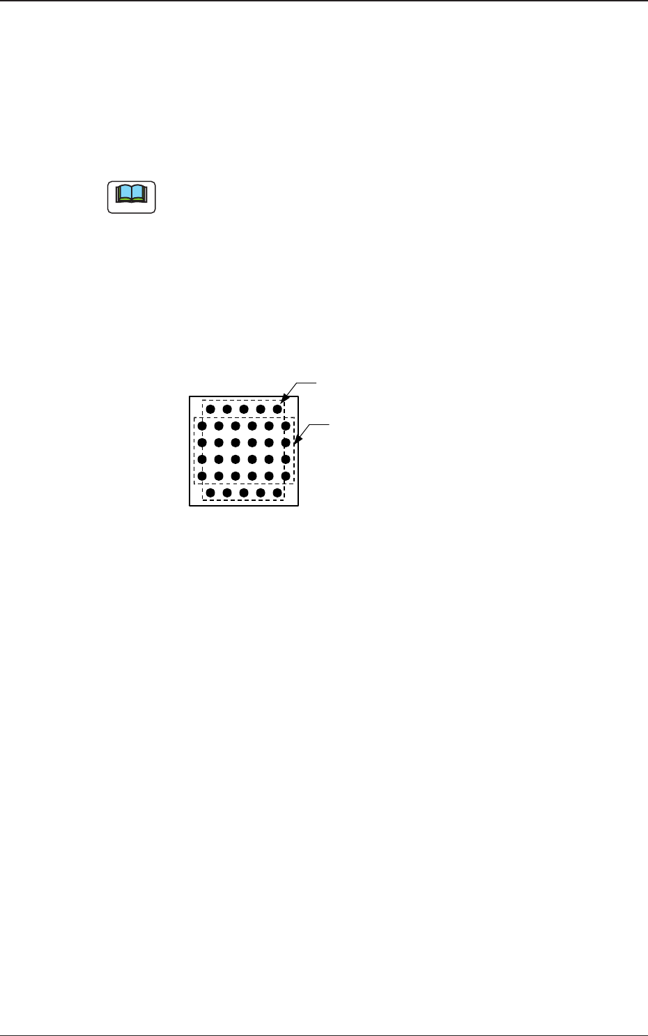
When the formation of a special BGA cannot be expressed by a certain
array type, such a BGA component can be used by increasing the
number of electrode groups.
Groups can be overlapped with each other.
Example : The balls arrayed in the 1st and 6th row are shifted by
half a pitch, compared with the balls in the other rows
(2nd through 5th rows).
Fig. 10
0606-002
4.2 Data Explanation (B01_13)
Bottom View of Components
Electrode Group 2
(2 rows and 5 columns)
Electrode Group 1
(4 rows and 6 columns)
Note