SOM-1802-002_w.pdf - 第50页
47 AJBES-P The figure shows the top view (electrode-missing side) of the component. Fig. 37 Individual Data Sheet (BGA/CSP) Minimum Unit: 0.001 mm 1 Mold size X [mm] 11 Missing Electd Block #1 Start Row 2 Mold size Y [mm…
46 AJBES-P
6. Measurement of Component Dimensions
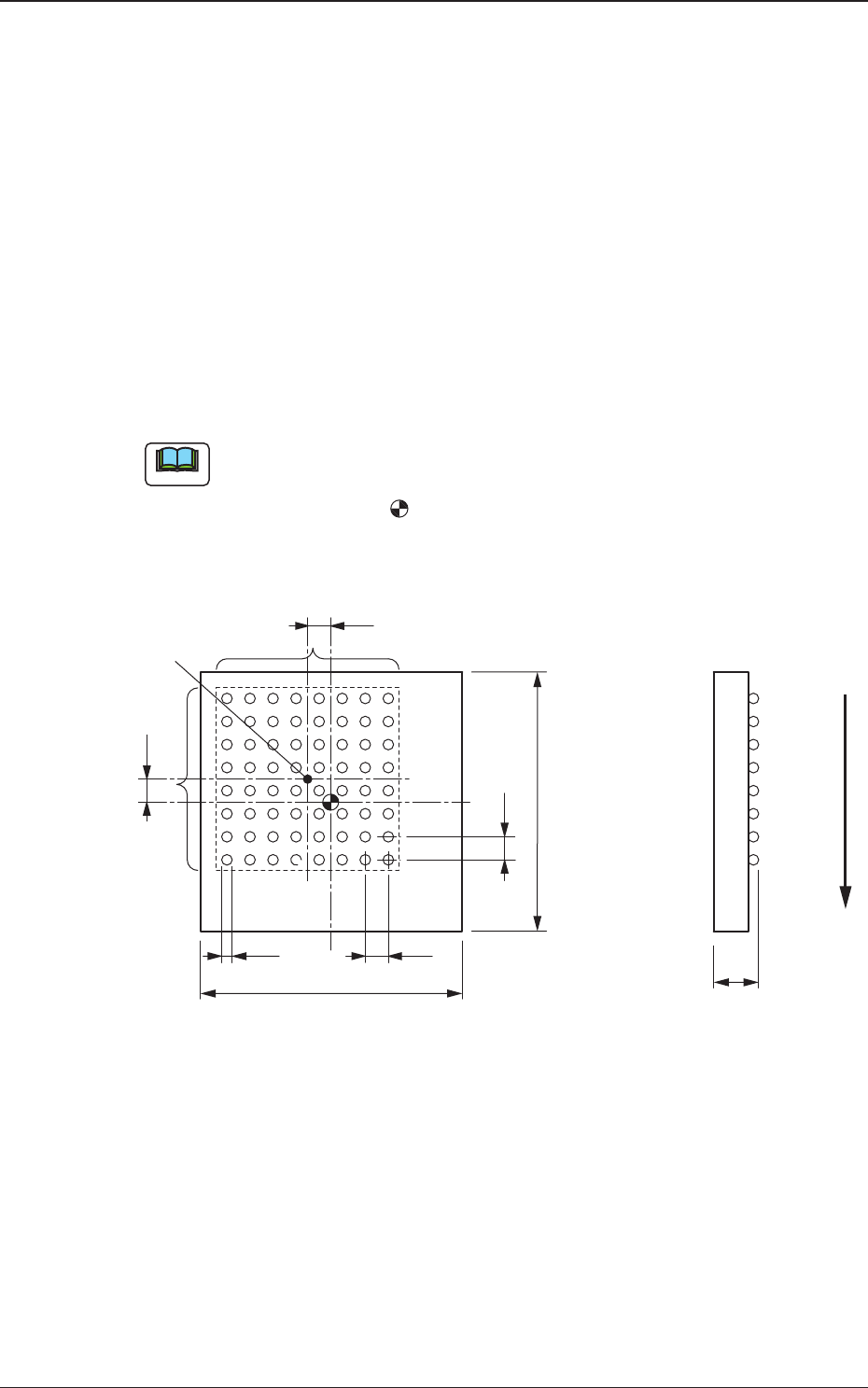
Measure the dimensions [1] through [10] in the figure.
When a component has several electrode groups, set "Enable" in the
"Extended setting" text box and measure the dimensions [5] through [10] for
Electrode Groups 2 and 6.
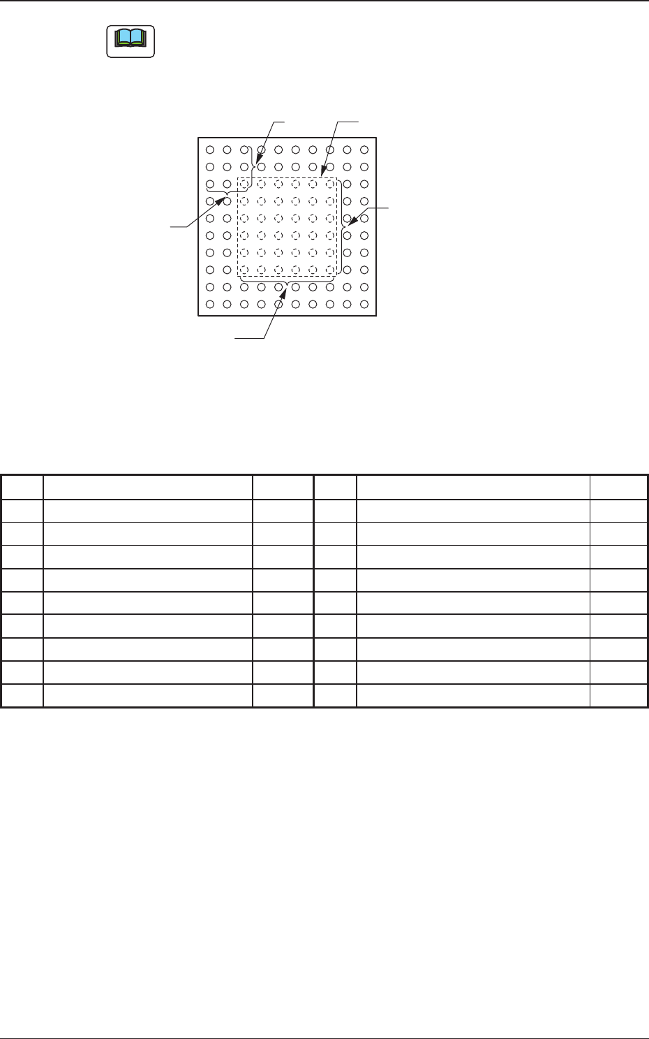
As for components with missing electrodes, set "Enable" in the "Extended
setting" text box and the number of missing blocks in the "# of Missing" text
box. After that, measure the dimensions [11] through [14] in the figure.
When there are several missing blocks, measure the dimensions [11] through
[14] for Missing Electrodes 2, 3 and so on.
(Up to 40 blocks can be specified as electrode-missing blocks.)
(a) The figure shows the top view (ball-missing side) of the component
and is an example of "# of Electrode Groups = 1"
(b) The center of the -mark is the reference point of the component.
(In normal cases, the reference point is located at the center of the
mold.)
Fig. 36
6. Measurement of Component Dimensions
Note
[4]
[6]
[7]
[2]
[9]
[8]
[3]
[1]
[10]
[5]
Center of
Electrode Group
User Direction of Feed
0606-002
47 AJBES-P
The figure shows the top view (electrode-missing side) of the
component.
Fig. 37
Individual Data Sheet (BGA/CSP)
Minimum Unit: 0.001 mm
1 Mold size X [mm] 11 Missing Electd Block #1 Start Row
2 Mold size Y [mm] 12 Missing Electd Block #1 Start Col
3 Mold size t [mm] [T [mm]] 13 Missing Electd Block #1 # of Rows
4 Electd Type #1 Dim 1 [mm] 14 Missing Electd Block #1 # of Cols
5 Grp No. 1 Grp Posn X [mm]
6 Grp No. 1 Grp Posn Y [mm]
7 Grp No. 1 Row Pitch [mm]
8 Grp No. 1 Col Pitch [mm]
9 Grp No. 1 # of Rows [pcs.]
10 Grp No. 1 # of Cols [pcs.]
6. Measurement of Component Dimensions
Note
[11]
[13]
[14]
[12]
1
123
2
3
Electrode-Missing Block
0606-002

48 AJBES-P0606-002
7. Troubleshooting after Error Window (Recognition Error ID)
7. Troubleshooting after Error Window
(Recognition Error ID)
Assuming "Recog Err ID", "Item (Error Name)", and "Description" in the
"ERROR" window as an index, the system retrieves the related page of the
instruction manual.
Refer to "7.2 Description of Recognition Error ID (Example)" for the
detailed description.