OM-1058-002.pdf - 第103页
Tg0409-PM-SO 9.8 Minimum Bending Radius 0410-002 102 9.8 Minimum Bending Radius Fig. 1 17 Minimum Bending Radius When the tape is bent with the minimum bending radius, the tape shall not be damaged, the components ahall …
Tg0409-PM-SO
9.6 Strength of Carrier and Cover Tapes
9.6 Strength of Carrier and Cover Tapes
Carrier Tape
When a tensile force of 10 N (1.02 kgf) is applied in the direction of
unreeling the tape, the tape shall withstand this force.
Cover Tape
When a tensile force of 10 N (1.02 kgf) is applied to the tape, the tape
shall withstand this force.
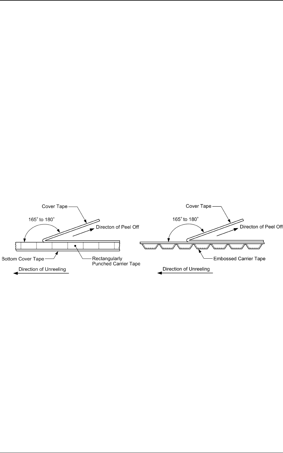
9.7 Peel Strength of Cover Tape
The direction of the cover tape peeling force should be maintained at an
angle of 165 to 180 degrees.
When the cover tape is peeled off at the speed of 300 mm/min +/- 10 mm/
min, the cover tape peeling force should be 0.1 to 0.7 N (10.2 to 71.4 gf).
Fig. 115 Angle in Peel Test Fig. 116 Angle in Peel Test
Rectangle Hole Punched
Carrier Type Taping
Embossed Carrier Type Taping
0410-002 101
Tg0409-PM-SO
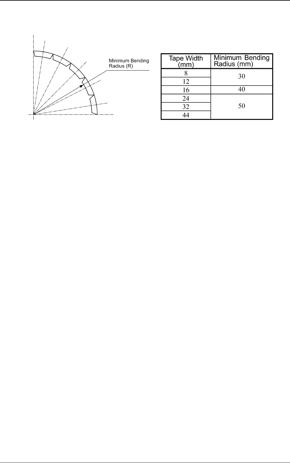
9.8 Minimum Bending Radius
0410-002 102
9.8 Minimum Bending Radius
Fig. 117 Minimum Bending Radius
When the tape is bent with the minimum bending radius, the tape shall not
be damaged, the components ahall maintain their position and direction in
the tape and shall be free from abnormalities such as damage.
Tape Width and Minimum Bending Radius
Table 30
Tg0409-PM-SO
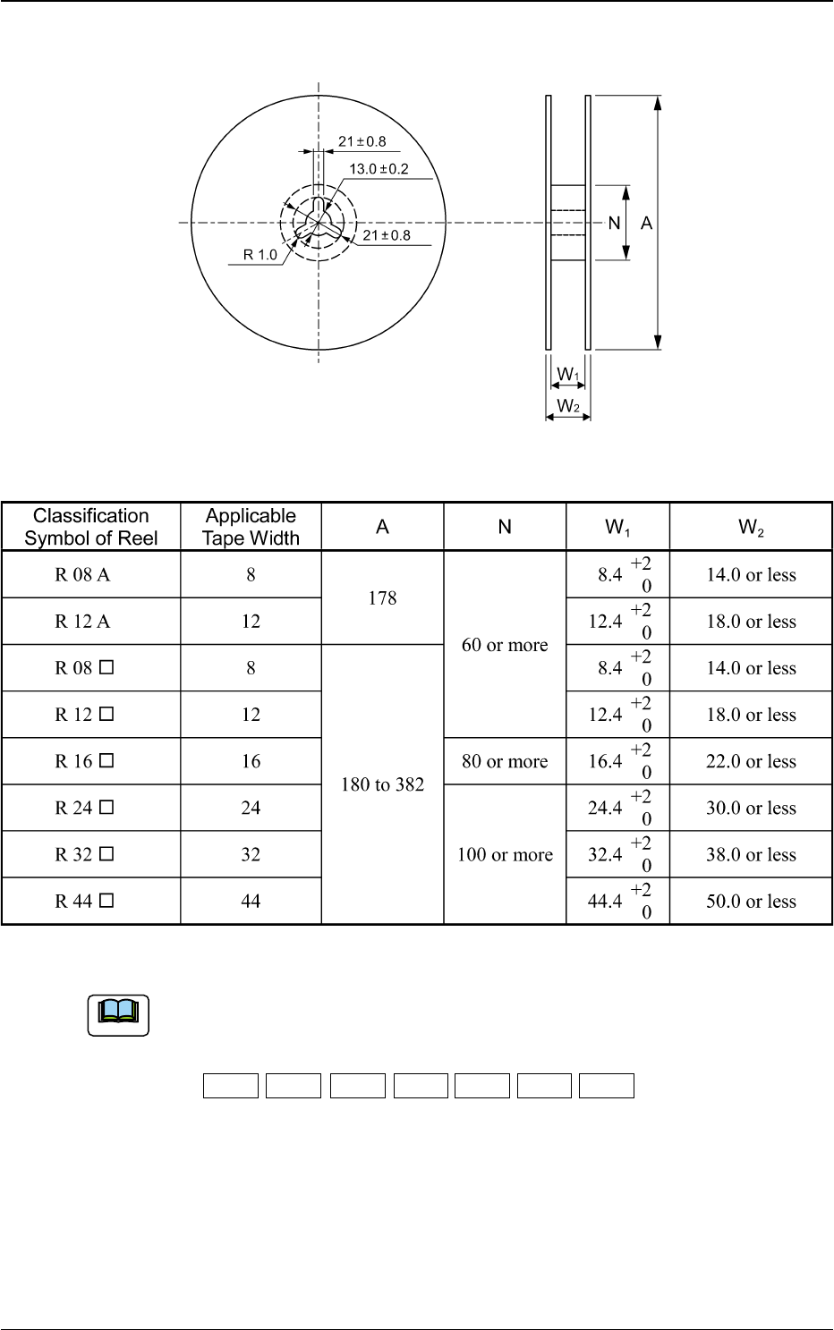
9.9 Style and Dimensions of Reel
9.9 Style and Dimensions of Reel
Fig. 118
Table 31
Unit : mm
0410-002 103
(a) A capital letter given below which corresponds to nominal value of
dimension A is entered into in classification symbol of reel.
The letter symbols are
A:178 B:180 C:254 D:330 E:360 F:370 G:382
(b) Dimension W2 means overall thickness of the reel.
(c) When "W2" in the table is exceeded, the reel may be locked at its center
shaft to cause a rotation failure.
Note