OM-1058-002.pdf - 第20页
Tg0409-PM-SO 0410-002 19 2.1 Attachment of T apes If there is any slack, it might cause cover tape take-up error or feed error . (16) T o feed the tape, press the feed lever as if there was a component on the pick-up pos…
Tg0409-PM-SO
(14) Attach the cover tape on the take-up
reel socket.
For tapes of 8 to 16 mm width, turn the
cover tape more than half-way around the
take-up reel socket, and catch it on the plate
spring.
Cut the cover tape if it has come out 2 to 3
mm from the plate spring.
Fig. 29
0410-002 18
2.1 Attachment of Tapes
Plate Spring
Cover Tape
Catch 2 to 3 mm of cover tape
and cut.
Note
Fig. 28
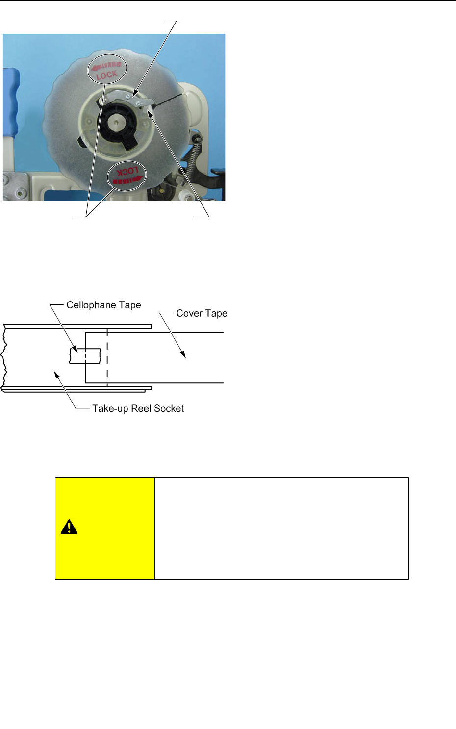
For tapes of 24 mm or wider, stick the cover
tape on the take-up reel socket with cello-
phane tape.
If the take-up reel socket is not set securely, the
take-up reel socket might come off during opera-
tion leading to a machine breakdown.
Turn the take-up reel socket in the arrow direction
(Refer to "Note" in Fig. 28) and make sure that the
plate spring is inserted until locked.
CAUTION
Tg0409-PM-SO0410-002 19
2.1 Attachment of Tapes
If there is any slack, it might cause cover tape take-up error or
feed error.
(16) To feed the tape, press the feed lever as
if there was a component on the pick-up
position.
Refer to "2.3 Component Pick-up Position
Alignment" for details.
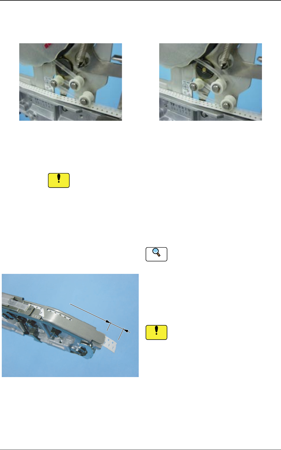
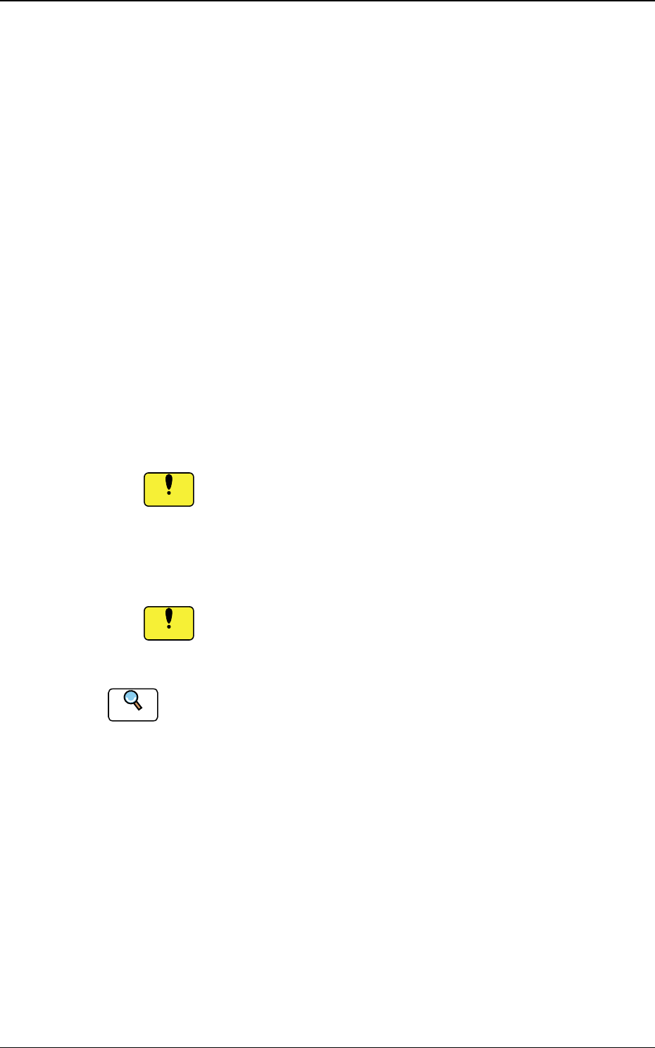
(17) The tape should be released from the
suppressor by 10 mm or less. If neces-
sary, cut any excess portion of the tape,
using scissors.
Do not tear the tape with your hand
because the pick-up position might be
deviated.
(15) Turn the take-up reel socket and pull the
cover tape so that there is no slack.
Fig. 30 No Slack on the Cover Tape
(OK)
Fig. 31 Slack on the Cover Tape
(NG)
Reference
Notice
Notice
10 mm or less
10 mm or less
10 mm or less
Fig. 32
Tg0409-PM-SO0410-002 20
2.2 Tape Detachment Procedure
(1) Detach the front hook from the pin.
At the same time, slide the hook while pushing the lower part of the
hook.
(2) Detach the suppressor holding lever from the suppressor hook
section.
At the same time, slide the suppressor holding lever while pressing the
lower part of the suppressor holding lever.
(3) Remove the cover tape from the take-up reel socket.
Cut the cover tape with scissors, leaving 300 mm or more of the end
from the suppressor (tape peeling section) for the preparation of next
attachment.
(4) Lift the suppressor and remove the cover tape through the slit
on the tape peeling section.
If a deformed cover tape is passed through the slit on the
tape peeling section, the tape peeling section might become
deformed leading to a pick-up error.
(5) Turn the take-up reel socket to take up the tape.
If the tape is pulled out while the cover tape is left on the
tape peeling section, the tape peeling section might become
deformed, which may cause pick-up error.
Refer to "2.1 Attachment of Tapes" for the positions of each section.
2.2 Tape Detachment Procedure
Notice
Notice
Reference