OM-1058-002.pdf - 第79页
Tg0409-PM-SO 8. Specifications of T ape Feeders 8.1 Specifications of 8 mm T ape Feeders (For Paper T ape) 0410-002 78 8. Specifications of T ape Feeders T able 16 The sizes of the components entitled "Referential C…
Tg0409-PM-SO0410-002 77
7.4 Tape cannot be set correctly
Table 15
7.4 Tape cannot be set correctly
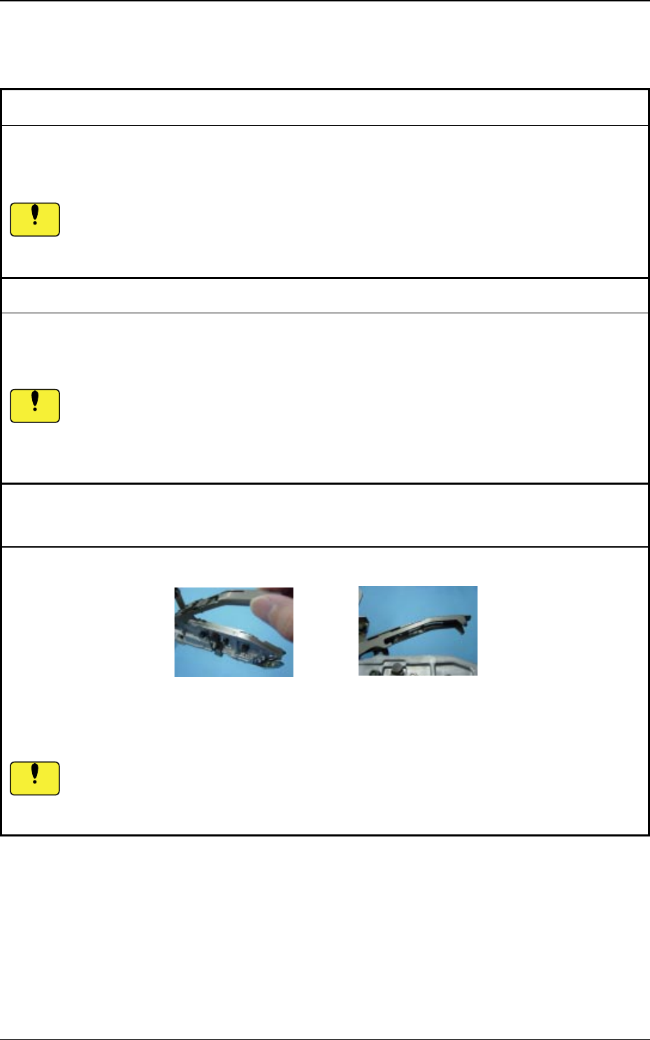
Remedy : Replace the front hook.
Reference Page : Pages 59 and 61
If the front hook at the tape feeder end is bumped, it might be deformed.
That could lead to an insufficient holding load on the suppressor, which might in turn cause a
pick-up error. Take care not to bump the front hook.
Cause : Front hook deformed
Cause : As there is a foreign substance between the chute section
and the suppressor, the tape is not satisfactorily held.
Remedy : Clean the chute section and the suppressor and remove the foreign substance.
Reference Page : Pages 10, 39 to 40 and 43
If the tape is attached while any foreign substance is there, it might cause suppressor
deformation or pick-up error.
Always remove any foreign substance.
Chute Section Suppressor (Rear Side)
Cause :Deformed Suppressor
Remedy : Replace the suppressor.
Reference Page : Pages 59 and 62
The suppressor is an important component that can greatly affect the pick-up rate.
If the tape feeder is dropped and any excessive force falls on the suppressor, then the
suppressor might be deformed.
Take the greatest care to handle the suppressor.
Notice
Notice
Notice
Tg0409-PM-SO
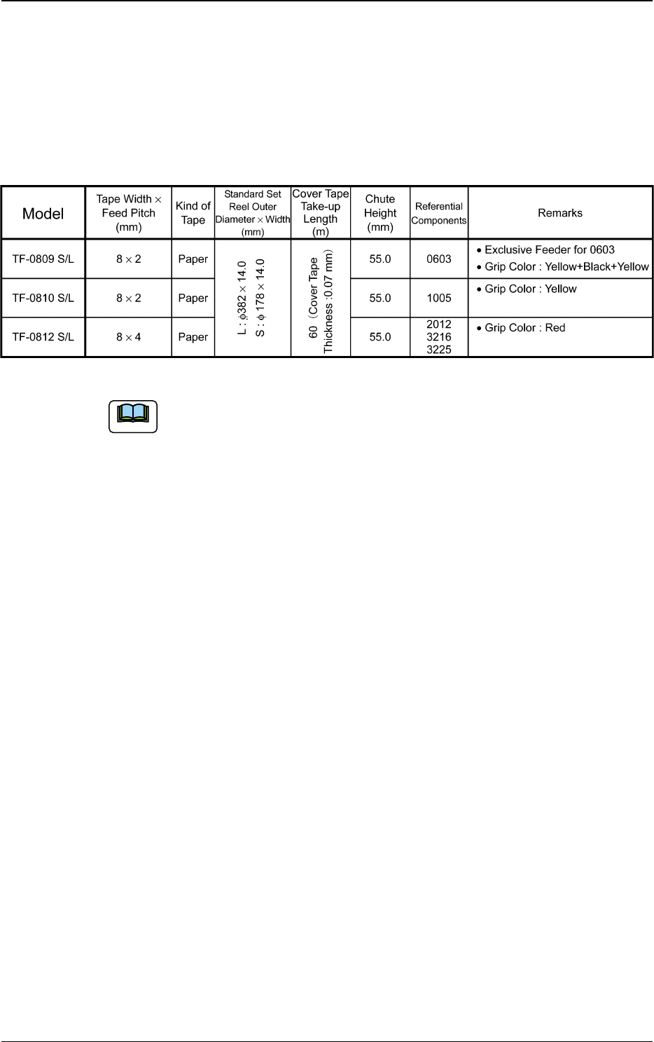
8. Specifications of Tape Feeders
8.1 Specifications of 8 mm Tape Feeders (For Paper
Tape)
0410-002 78
8. Specifications of Tape Feeders
Table 16
The sizes of the components entitled "Referential Components" differ
depending on the component makers.
The components are shown as types for your reference.
Note
Tg0409-PM-SO
8.1 Specifications of 8 mm Tape Feeders (For Paper Tape)
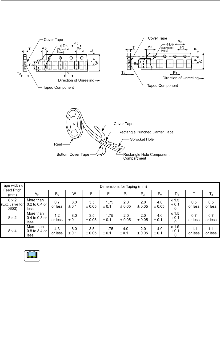
8.1.1 Referential Dimension For Taping
Fig. 89 Rectangle Hole Pitch (2 mm) Fig. 90 Rectangle Hole Pitch (4 mm)
Fig. 91
Table 17
Rectangle Hole Punched
Carrier Type Taping
Rectangle Hole Punched
Carrier Type Taping
(a) A0 × B0 stands for the rectangle hole size on the tape.
The clearance between a rectangle hole and a component affects the pick-
up rate. Use the taping component with appropriate clearance specifica-
tions.
(b) The above specifications do not imply any guarantee of pick-up rate, etc.
The pick-up rate varies depending on how the main machine is adjusted
and the combination of the main machine and the tape feeders.
(c) The clearance between the centerlines of the cavity and the sprocket hole
should be 0.05 mm or less.
(d) 10 pitches cumulative tolerance P0 should be ± 0.2 mm.
(e) The cover tape should run smoothly along the sprocket holes. The edges
of the cover tape should be aligned with the carrier tape (taping).
The thickness of the cover tape should be 0.07 mm or less (including
waste paper).
0410-002 79
Note