SMN-Tape Feeder Manual(Eng Ver5).pdf - 第28页
Samsung SM-Series Pneumatic T ape Feeder Users' Manual 1-10 1.4. IT and Non-IT St andard 1.4.1. NON-IT Function Probe Pin Components 7 9 11 8 10 Figur e 1-8. Non-IT Pr obe Pin Layout T able 1-5. Probe Pin Assignme…
Overview
1-9
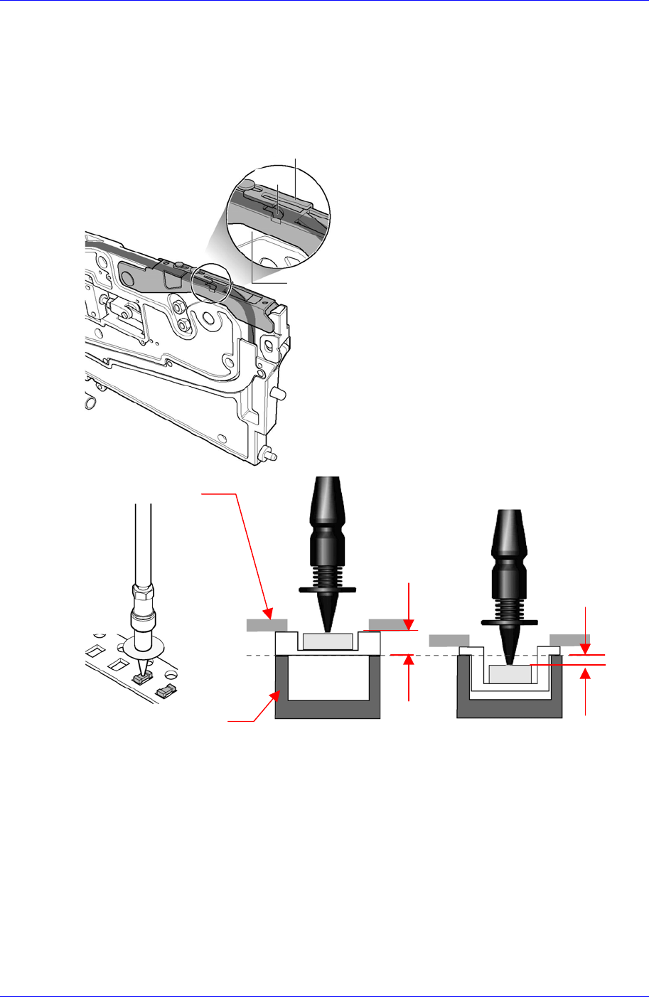
1.3. Reference plane for Z-axis height of SM tape feeder
The reference plane for Z-axis height of the SM tape feeder is beneath (above the main
frame) the tape at the pickup position.
Consequently, height of Z-axis at the pickup position is diverse according to the thickness
of the transportation tape.
The Z value of the pickup point is applied in various ways according to the types of tape
feeders. In addition, it varies depending on the types of supplied tape. In the case of the
embossed tape, the height must be set lower than that of the paper tape.
For embossed tape, set the Z value of the pickup point properly referring to the
component tape standards.
Tape Guide
Tape
Frame
Reference
Surface
Z = 0
Paper Tape Embossed Tape
Z > 0
Z < 0
Ta
p
e Guide
Frame
Samsung SM-Series Pneumatic Tape Feeder Users' Manual
1-10
1.4. IT and Non-IT Standard
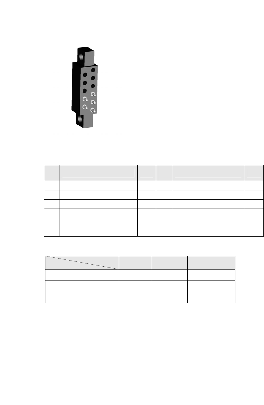
1.4.1. NON-IT Function
Probe Pin Components
7
9
11
8
10
Figure 1-8. Non-IT Probe Pin Layout
Table 1-5. Probe Pin Assignment (Non IT)
Pin
No.
Function Use
Pin
No.
Function Use
1 ID0 X 7 Indexing Signal O
2 ID1 X 8 Clamping Signal O
3 D24V X 9 Indexing Command O
4 Communication X 10 F24V O
5 Communication X 11 F24G O
6 D24G X
LED Status
Status
Color
Off Green Orange
Clamped & Shutter Close O
Shutter Open O
Unclamped O
Overview
1-11
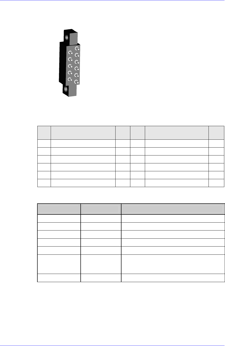
1.4.2. IT Function
Probe Pin Components
1
3
5
7
9
11
2
4
6
8
10
Figure 1-9. IT Probe Pin Layout
Table 1-6. Probe Pin Assignment (IT)
Pin
No.
Function Use
Pin
No.
Function Use
1 ID0 O 7 Indexing Signal O
2 ID1 O 8 Clamping Signal O
3 D24V O 9 Indexing Command O
4 Communication O 10 F24V O
5 Communication O 11 F24G O
6 D24G O
LED Status
Feeder State LED Display * To indicate:
Not Powered Off Power is not supplied to the feeder
Normal(Ready) Green Feeder is ready
Not Connected Green Blink Not connected to CAN Master
Feeding(Busy) Orange Parts supply in progress (Busy)
Warning Orange Blink Feeder is in warning status (Warning)
Mismatching Red Blink Discrepancy between the feeder
arrangement information in the PCB program
and the actual feeder arrangement
Error Red Feeder is in error status (Error)